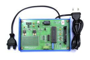
GSAS Micro systems manufacture a variety of interface modules useful for teaching/training/lab use.
Most of the interface modules are supplied in a standard plastic enclosure and every interface module is shipped with interconnecting cables and accompanied by a user’s manual which provides detailed installation cum operational instructions, the theory of the interface including sample programs to illustrate various features of the module. The following are the types of interfaces that we deal with, please click on any of the panes below for more information
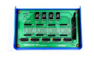
7 - segment Display interface
This interface provides a four digit 7-segment display driven by the output of four cascaded shift registers. Data to be displayed is transmitted serially (bit by bit) to the interface. Each bit is clocked into the shift register by providing a common clock through a port line. Thus one port line provides the data and another port line provides the clock.
This interface allows the user to study 7-segment display control techniques, code conversion methods, etc., The software exercise could include procedures for table look-up, a variety of bit manipulation operations, etc.
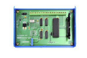
8 Bit 16- Channels ADC interface
This interface provides 16 Channel, 8-bit ADC, based on ADC 0816 – 16 channel 8bit data acquisition device. Provision is made for on-board reference voltage generation using precision voltage regular LM 723. The interface has 20 pin terminal strip to feed in the analog voltages, the input signal voltage range is 0-5V
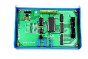
12 Bit 8- Channel ADC interface
This interface is based on Analog Device AD1674, ADC with 12-bit, 10 usec sampling rate. AD1674 has a built-in sample and hold amplifier too. The ADC accepts Unipolar (0-10V) or Bipolar (±10V or ±5V) signal inputs. Provision for an optional 8 channel multiplexer, ADG 508. The channels can be configured to accept current (4-20mA) or voltage signals. The interface has 9 pin terminal strip to feed the analog input voltages.
Calculator Keypad interface
This interface module provides a calculator style calculator keypad consisting of the switches 0 to 9, +, -, x, =, %, ., C, CE, etc., These 20 switches are arranged in a 3×8 matrix (the third row has only 4 switches ). The row lines can be driven through port C (Bits PC2, PC1 and PC0) and the status of column lines can be read through port A. This interface allows the use to study a number of techniques generally used
in the calculator.
A User can write programs for software debouncing of key closures, two-key lockout, keyboard encoding and parsing etc., to gain a good understanding of keypad interface. User can become familiar with the processor’s arithmetic instructions by implementing the calculator functions like Addition, Subtraction, Multiplication, Division, etc.,
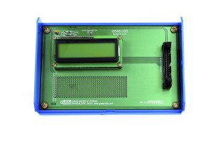
16 X 2 LCD interface
LCD modules are widely used in areas where information is conveyed for viewing. They can be seen in calculators, mobile and cellular phones, pagers and other electronic products.
The interface is built around 16×2 (sixteen character per line and two Lines) alphanumeric LCD module. This can be directly coupled to the Any of I/O lines. This present interface module allows the user to become familiar with the techniques of using the LCD module.
DAC For ADC & TEMP Sensor interface
This interface consists of an 8-bit D/A converter (DAC) and a comparator. The user can control the input to the DAC through a port (the port output is latched and presented as input to the DAC). The DAC output and Analog Input are fed to a comparator whose output can be monitored through another port line. A key, whose status can be read through a port line, is also provided. User routine can read this key status to determine when to start the conversion.
This interface allows the user to implement A/D conversion using DAC through successive approximation technique or counter technique. Also provides a simple temperature sensor simulator consisting of a TTL mono shot, allowing the user to employ a thermistor to convert a physical parameter like temperature to its equipment digital code.
DC Motor interface
The DC motor used in this interface module is of rating +12V at 250mA. This Interface is used to control the speed of the motor. The pulse width modulation technique is used to vary the speed of DC Motor. The frequency of the pulse is 100Hz keeping the frequency constant, the Width of the pulsed is used to change the speed. The ramp and pedestal technique is used to change the pulse width and thereby the speed.
DC motors can be used in various application like robots, sewing machines, grinders Lathe, precision high-speed drilling and milling spindles, etc.,
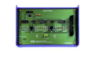
DUAL DAC interface
This interface consists of two 8-bit D/A converters whose current outputs are converted to voltage outputs using operational amplifiers. These Voltages (Ports outputs) are available to the user. The inputs to the DACs can be controlled through I/O ports. A sample program is provided with the interface to generate a triangular/ square waveform. The waveform can be observed on CRO .
The user can write separate programs to generate other waveforms like a sine wave, sawtooth, etc.
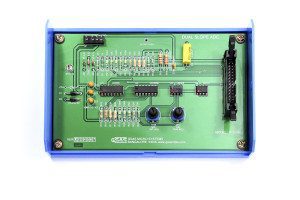
DUAL SLOPE ADC interface
This interface consists of an integrator and a comparator. A port line can be used to control a CMOS analog switch to reset the integrator, another port line can be used to control another CMOS analog switch to allow the integration of an analog input (the duration of integration is controlled by user software). and yet another port line can be used to control another CMOS analog switch to allow the integration of standard reference voltage (the duration of which can be measured by user software). The integrator output fed to a comparator and the comparator output, in turn, can be sensed through a port line.Offset trimming provision is available for the integrator and comparator.
This interface helps the user to understand the principle of Dual Slope ADC and to write software for implementing it and observe the switching waveforms
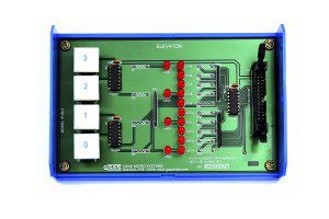
Elevator interface
This interface simulates the control and operation of an elevator. Four floors are assumed and for each floors, a key and corresponding LED indicator is provided to serve as request buttons and request status indicators. The elevator itself is represented by a column of ten LEDs. The motion of the elevator can be simulated by turning on successive LEDs, one at a time. The delay between turning OFF one LED and turning ON the next LED can simulate the “speed” of the elevator. The user can use different I/O lines to read the request status information, reset indicators and control the elevator (LED column).
The interface allows the user to write software for simulating the operation of the elevator. The software exercise could include priority schemes, different Service schemes, etc.
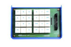
Keyboard Display interface
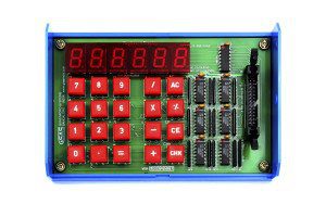
This keyboard display interface provides a calculator-style keyboard with seven segment displays. It consists of the switches 0 to 9, =,-,x,/,%, AC, CE, CHK and six 7-segment display. The 20 keys are arranged in a 4×5 matrix (each row has 5 keys).
This interface allows the user to study a number of techniques generally used in calculator keyboard interfacing. The user can write programs to gain a good understanding of keyboard display, Arithmetic group of processor instructions by implementing the calculator functions (+,-./=,%, etc.).
Logic Controller
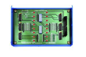
This interface consists of eight TTL buffered outputs and eight TTL buffered inputs.The logic state of each input/output is indicated by a corresponding LED (ON/OFF). The inputs can be read through one port and the outputs can be controlled through another port. The inputs and the outputs are brought to berg-pins.
Two Dip-Switches SW1 and SW2 are also provided. SW1 is used to connect the output status to the corresponding input line when switch is ON. SW2 is used to set different logic states by setting the switch to ON (or) OFF.
Music Tone Generator
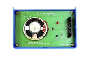
This interface consists of a transistor and a speaker. The transistor is driven by a port line and the transistor, in turn, amplifies the signal and drives the speaker. By controlling ON/OFF periods of the port line through software, the user can generate the required musical note. Sample programs are provided to generate a variety of musical notes.
Stepper Motor Interface
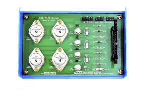
This interface consists of a stepper motor ( +12V/ +5V DC,3 Kg. Cm torque), Power Supply and required driver circuitry along with the necessary software to control the operation of the stepper motor. This interface permits ON/OFF control of the individual coils of the stepper motor at varying speeds in either direction
Temperature Transducer interface
This interface is used to control the temperature by interfacing a Resistance Temperature Detector (RTD) with a microprocessor. The RTD converts a change in temperature to change in Resistance. The change in resistance is converted into a change in voltage using a / resistance bridge. By using ADC 7109 the voltage is converted into digital form and fed to the microprocessor to switch the relay for closed loop operation.

