
 Pico Technology
 Pico Technology Oscilloscope Knowledge Base
Oscilloscopes & AnalyzersTechnical guides, application notes, and oscilloscope fundamentals from Pico Technology, bandwidth, sampling, resolution, triggering, FFT, and protocol decoding. India support via GSAS.
Topics
Oscilloscope fundamentals, measurement techniques
Guides
50+ application notes
Formats
Articles, videos, webinars
Access
Free on picotech.com
Overview
About Pico Technology Oscilloscope Knowledge Base
Pico Technology maintains one of the most comprehensive oscilloscope knowledge bases in the test and measurement industry, covering everything from fundamental concepts to advanced measurement techniques. This page is a curated guide to the key topics, whether you are selecting your first oscilloscope, optimizing a measurement setup, or integrating PicoScope into an automated test system, the resources below and on Pico’s knowledge base will help you get the most from your instrument.
Oscilloscope Fundamentals
Understanding oscilloscope specifications is essential for selecting the right instrument and interpreting measurements correctly. The core parameters that define an oscilloscope’s capability are bandwidth, sampling rate, resolution, and memory depth, and they interact in ways that are not always intuitive.
Bandwidth determines the highest frequency signal an oscilloscope can accurately measure. It is defined as the frequency at which the oscilloscope’s response falls to -3 dB (approximately 70.7%) of the input signal amplitude. A common rule of thumb is to select an oscilloscope with at least 5x the bandwidth of the highest frequency component in your signal to capture fast edges faithfully. For example, a 50 MHz digital signal with fast rise times may contain harmonics up to 250 MHz or higher, requiring a 200-500 MHz oscilloscope for accurate edge representation.
Sampling rate determines how many data points the oscilloscope captures per second. The Nyquist theorem requires at least 2x the signal frequency, but practical measurements need 5-10x oversampling for accurate waveform reconstruction. A 1 GS/s sample rate provides 10 points per cycle on a 100 MHz signal, adequate for most measurements, but demanding applications like jitter analysis may benefit from higher rates.
Resolution (measured in bits) defines the oscilloscope’s ability to distinguish small voltage differences. An 8-bit oscilloscope divides the input range into 256 levels. A 12-bit oscilloscope provides 4096 levels, a 16x improvement in voltage resolution. Pico Technology’s FlexRes oscilloscopes (PicoScope 4000, 5000 Series) offer adjustable resolution from 8 to 16 bits, allowing engineers to optimize for either bandwidth or voltage sensitivity depending on the measurement.
Memory depth determines how long a capture the oscilloscope can store at full sample rate. Deep memory (256 MS to 2 GS in PicoScope models) enables long-duration captures at high sample rates, critical for capturing rare events, analyzing protocol sequences, and performing spectrum analysis on extended signal segments.
For the full treatment of these topics with interactive examples, visit the Pico Technology oscilloscope knowledge base.
Measurement Techniques
Even a high-specification oscilloscope produces inaccurate results if the measurement setup introduces errors. Probing technique, grounding, and input configuration are the most common sources of measurement artifacts.
Probing is where most measurement errors originate. Passive probes (typically 10:1 attenuation) are adequate for general-purpose measurements up to the probe’s rated bandwidth, but their input capacitance (8-15 pF) can load high-impedance circuits. Active probes with sub-picofarad input capacitance are essential for fast signals on high-impedance nodes. Probe compensation (adjusting the trimmer capacitor for flat square-wave response) should be verified every time a probe is connected.
Grounding artifacts are the second most common source of misleading oscilloscope measurements. The long ground lead included with most probes acts as an antenna at frequencies above a few tens of MHz, adding ringing and overshoot to the displayed waveform that does not exist in the actual signal. Using the shortest possible ground connection, a spring-tip ground contact or a coaxial probe tip, dramatically improves high-frequency measurement fidelity.
Differential measurements are required when neither side of the signal under test is referenced to the oscilloscope’s ground. Measuring across a current-sense resistor in a high-side driver, or capturing a floating gate drive signal, demands either a differential probe or two-channel math subtraction with matched probes. Failing to use differential techniques in these situations risks damaging the oscilloscope or the circuit under test.
For detailed probing guides and grounding best practices, see the Pico Technology knowledge base.
Advanced Features
Modern oscilloscopes like the PicoScope range include analysis capabilities that extend far beyond basic waveform display. Understanding these features enables measurement workflows that previously required specialized instruments.
FFT and spectrum analysis transforms time-domain captures into frequency-domain displays, revealing harmonic content, noise sources, and EMI characteristics without a separate spectrum analyzer. PicoScope 7 software provides multiple FFT window functions (Hanning, Blackman, Flat Top, and others), peak hold, and average spectrum modes. Deep memory is particularly valuable for FFT work: more time-domain data points produce higher frequency resolution in the spectrum, enabling separation of closely spaced frequency components.
Protocol decoding turns raw oscilloscope waveform data into decoded bus transactions for serial protocols including I2C, SPI, UART/RS-232, CAN, CAN FD, LIN, FlexRay, I2S, and others. PicoScope 7 displays decoded data as color-coded annotations overlaid on the waveform, with the ability to trigger on specific data patterns, addresses, or error conditions. This eliminates the need for a separate protocol analyzer in many embedded development workflows.
Math channels provide real-time computation on live or captured waveforms, addition, subtraction, multiplication, integration, differentiation, and custom formulas. Combined with measurement statistics (mean, RMS, peak-to-peak, rise time, frequency) and mask limit testing (automated pass/fail against a tolerance template), these features enable production-grade automated verification directly in PicoScope software.
Explore the full capabilities in the Pico Technology knowledge base.
Application Areas
PicoScope oscilloscopes and the techniques in the knowledge base apply across a wide range of industries and measurement challenges.
Automotive electronics is one of Pico Technology’s strongest application domains. PicoScope is the standard tool for automotive diagnostics in workshops and R&D labs worldwide, with specialized protocol decoders for CAN, CAN FD, LIN, FlexRay, and SENT. Application notes cover ECU signal analysis, injector waveforms, ignition system testing, EV battery management, and ADAS sensor validation.
Power electronics measurements, switch-mode power supply characterization, inverter waveform analysis, power factor measurement, and efficiency testing, demand oscilloscopes with high resolution, wide dynamic range, and the ability to handle high-voltage differential signals. The knowledge base covers probe selection for power measurements, safe connection practices for high-voltage circuits, and power analysis math channel configurations.
EMC pre-compliance testing uses PicoScope’s FFT and spectrum analysis capabilities to identify radiated and conducted emissions before formal compliance testing. The deep memory and wide bandwidth of PicoScope 6000E Series instruments enable near-field probe scanning, conducted emissions measurement, and transient event capture that helps engineers find and fix EMI issues early in the design cycle.
IoT and embedded systems development benefits from PicoScope’s protocol decoding (SPI, I2C, UART for sensor buses; BLE and Wi-Fi debugging via analog signal inspection), low-power measurement capability (using PicoScope in high-resolution mode to capture sleep current transitions), and SDK-driven automated testing for firmware validation.
For application-specific guides and case studies, visit the Pico Technology knowledge base.
PicoScope Software and SDK
PicoScope 7 is the measurement software included free with every PicoScope oscilloscope, running natively on Windows, macOS, and Linux. It provides a modern, touch-friendly interface with multi-window waveform display, persistence modes, serial decoding, math channels, mask testing, and reference waveform comparison. Software updates are free for the life of the product, and new features, protocol decoders, and performance improvements are released regularly.
PicoSDK is the programming interface for engineers who need to control PicoScope from their own applications. It provides APIs and example code for C, C#, Python, MATLAB, and LabVIEW, with drivers for Windows, macOS, and Linux (including ARM/Raspberry Pi). PicoSDK supports block mode (triggered capture), streaming mode (continuous data flow), and rapid block mode (fast sequential acquisitions), enabling integration into automated test systems, custom data loggers, and production line equipment. The knowledge base includes getting-started guides for each supported language and example projects demonstrating common measurement automation patterns.
For software tutorials, SDK programming guides, and PicoScope 7 tips, see the Pico Technology knowledge base.
Watch the Pico Technology Oscilloscope Knowledge Base introduction
GSAS Micro Systems is an authorized Pico Technology partner in India. For oscilloscope selection guidance, application support, or PicoSDK integration assistance, contact the GSAS technical team.
Blog
Pico Technology Insights
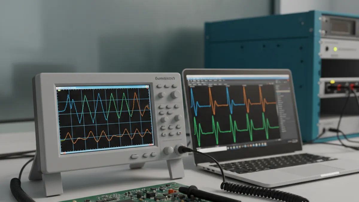
How to Buy an Oscilloscope in India (2026): USB vs Benchtop, Bit Depth, Bandwidth: A Buying Guide
A vendor-neutral buying guide for Indian engineering teams choosing an oscilloscope in 2026. How to size bandwidth, sample rate, channels and bit depth; when a USB/PC oscilloscope beats a benchtop; and how oscilloscope price in India actually breaks down once you add GST, probes and warranty. Written for embedded, power and education teams in Bengaluru, Pune, Chennai, Hyderabad, Mumbai and Delhi NCR.
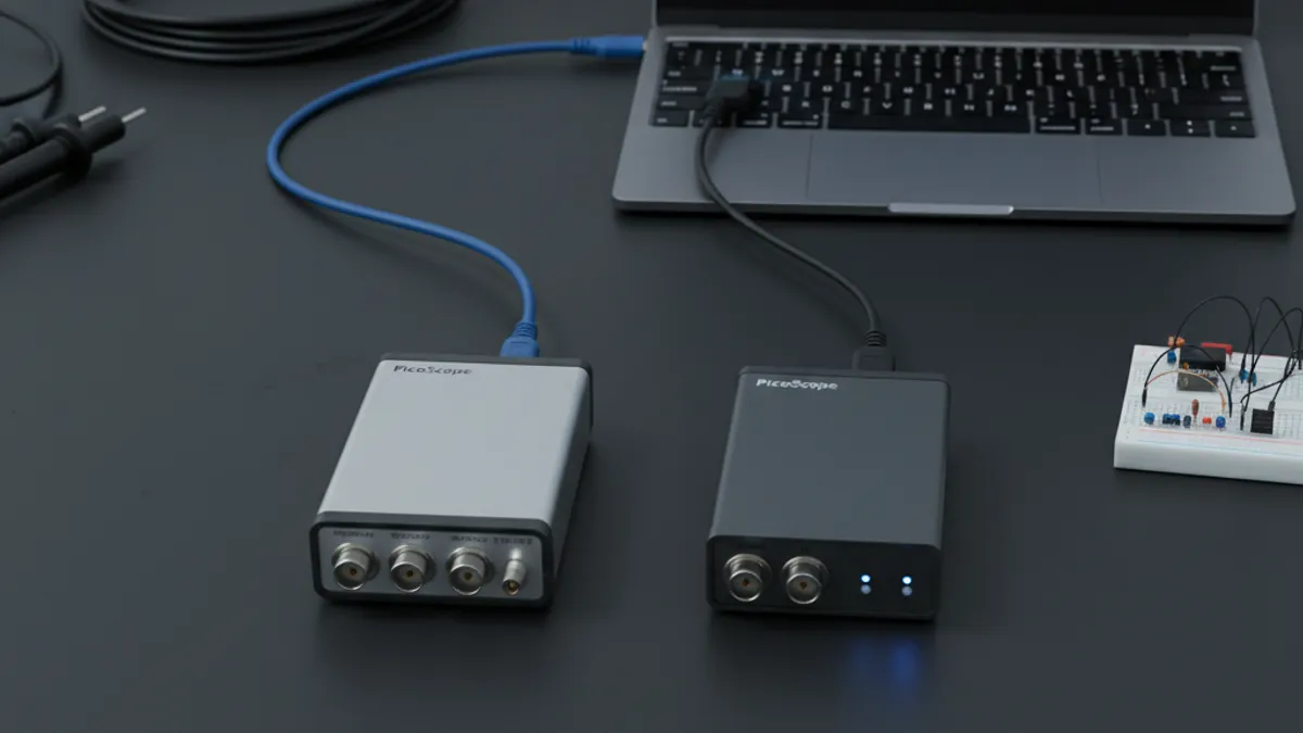
PicoScope 5000D vs 5000E: Native 16-Bit or FlexRes? A Buyer's Guide for Indian Labs
The established PicoScope 5000D FlexRes switches between 8-bit and 16-bit; the new PicoScope 5000E gives you native 16-bit always on. A verified, spec-by-spec buyer's guide for Indian labs choosing between them, with 5444D vs 5464E framing and India procurement notes from GSAS.
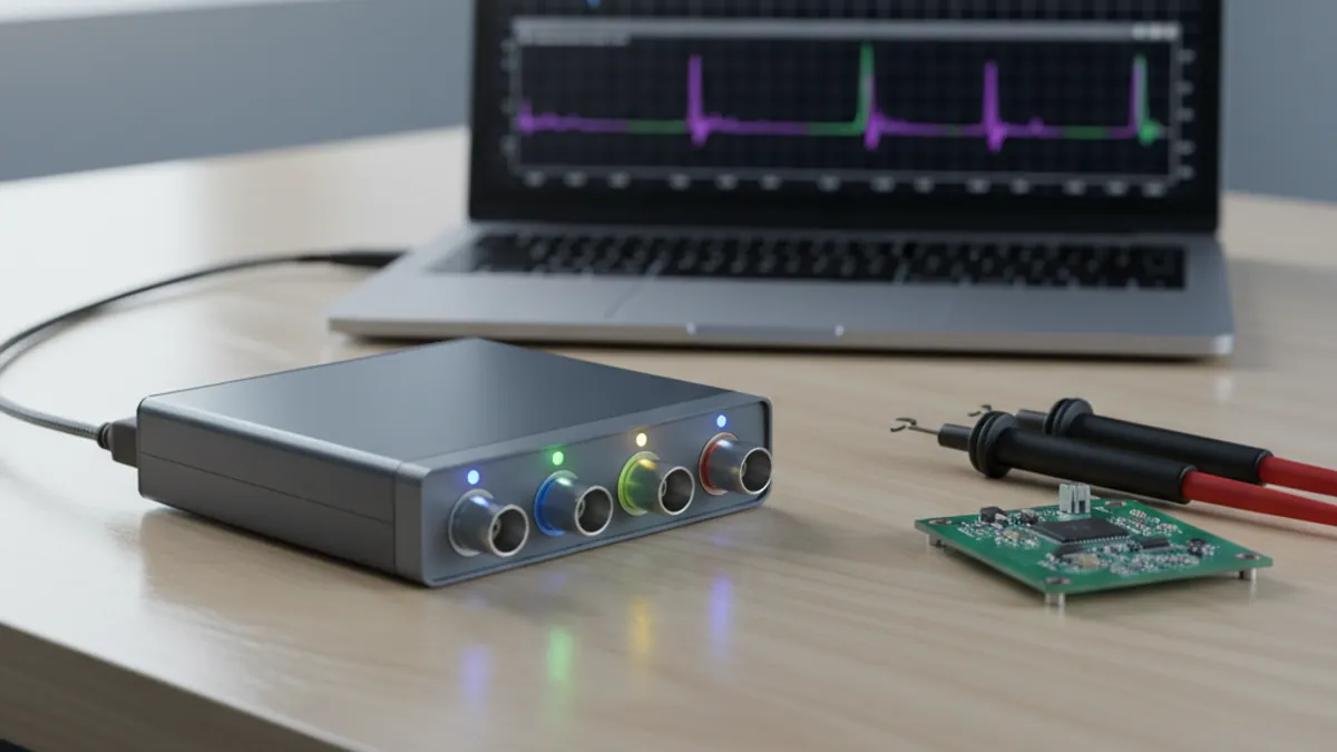
PicoScope 5000E in India: The World's First 4-Channel 16-Bit USB Oscilloscope, Explained
Pico Technology launched the PicoScope 5000E on 28 May 2026, the world's first 4-channel 16-bit USB oscilloscope. Verified specs, the 5462E/5463E/5464E and Plus models, and how to buy the 5000E in India through GSAS.
Related products
More from Pico Technology
All Pico Technology products →
Interested in Pico Technology Oscilloscope Knowledge Base?
Get pricing, an evaluation unit, or a technical consultation from our application engineers.