
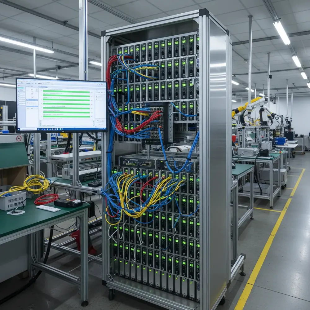
Production test systems frequently need multiple Promira Serial Platforms running simultaneously, one per DUT station, or multiple per station for different protocol requirements. When integrating the Promira with NI LabVIEW and TestStand, intermittent error 8030 from `ps_queue_submit` can occur if the API handles and queue lifecycle are not managed correctly.
Understanding Promira Queues
The Promira API uses a queue-based architecture for I2C and SPI transactions. Rather than executing each command individually (which would incur USB or Ethernet round-trip latency for every transaction), the API accumulates multiple commands into a queue and submits them as a batch:
1. Build the queue: add I2C write, I2C read, SPI transfer, and delay commands.
2. Submit the queue: `ps_queue_submit` sends the entire batch to the Promira hardware for autonomous execution.
3. Collect results: `ps_queue_result` retrieves the outcomes of each command in the queue.
This queue architecture is what enables the Promira’s gap-free SPI streaming at 20 MHz and beyond, by keeping multiple outstanding queues in the Promira’s execution pipeline, the hardware can execute one queue while the host prepares the next, eliminating PC-to-instrument latency from the bus timing.
Root Cause: Concurrent Handle Access
The error PS_APP_PENDING_ASYNC_CMD (code 8030) occurs in two scenarios:
Race condition: Two parallel LabVIEW threads or TestStand sequences access the same Promira handle simultaneously. The Promira API is not thread-safe per handle, if thread A submits a queue while thread B is still collecting results from a previous queue on the same handle, the API returns error 8030. Uncollected results: If a previous queue’s results were not collected via `ps_queue_result` before submitting a new queue, the Promira reports pending async commands. The queue is not automatically cleared after execution.
The Fix
For race conditions: Add a 10–20 ms delay between consecutive transactions on the same handle, or use a mutex/semaphore in LabVIEW to serialize access to each Promira handle. Each physical Promira should have exactly one thread accessing its handle at any time. For uncollected results: Always call `ps_queue_result` after every `ps_queue_submit` before building and submitting the next queue. The pattern should be: build → submit → collect → build → submit → collect. For maximum throughput: Create multiple queues and submit them rapidly, the Promira hardware can hold several outstanding queues in its execution pipeline and execute them autonomously without PC intervention. This is how 20 MHz gapless SPI streaming is achieved: the host fills the pipeline faster than the Promira drains it.
Multi-Promira LabVIEW Architecture
When running N Promira platforms in a single TestStand system:
- Open each Promira with its own handle (`ps_open` returns a unique handle per device).
- Assign each handle to its own LabVIEW worker thread or TestStand socket.
- Never share a handle between threads, each handle is a private resource.
- Use the Promira’s serial number or Ethernet IP address to consistently identify which handle maps to which DUT station.
The Promira’s Gigabit Ethernet interface is particularly valuable in multi-unit test systems because it eliminates USB hub reliability issues and enables placement of each Promira directly at its test station with a standard Ethernet cable run.
GSAS Support
GSAS Micro Systems provides applications engineering support for multi-Promira test system integration, including LabVIEW VI architecture guidance, TestStand sequence design, and Ethernet networking configuration for production floor deployments across India.
Also appears in:
Interested in Total Phase tools?
Talk to our application engineers for personalized tool recommendations.
More from Total Phase
View all →
Aardvark vs Cheetah vs Promira: Total Phase Host Adapter Guide (India)
17 Jul · 6 min
Automated EV Charger Test Bench in India: GW Instek AC Source, DC Load and Battery Emulator
6 Jun · 16 min
Best Logic Analyzer in India (2026): A Vendor-Neutral Buying Guide for Embedded Teams
5 Jun · 10 min
Capturing I²C/SPI Data to Train Edge AI: A Protocol-Analyzer Workflow for Indian Embedded Teams
4 Jun · 9 min

Emulating Processor Power for Thermal Testing: Why Constant Power
7 Oct · 7 min

CRPS and Rack Power Supply Testing: The Six Tests That Matter
7 Oct · 7 min


