Technical case study: EV charger test and validation. Study by Karthick N (Senior Field Applications Engineer) and Dilip K (Field Applications Engineer), GSAS Micro Systems. A downloadable PDF of this case study is linked at the end.
This automated EV charger test bench validated a CAN-controlled EV scooter charger across the full Indian grid envelope, with no live battery pack in the loop, unattended overnight regression, and one automated compliance report covering grid sweep, state-of-charge (SoC) sweep, mode switching and protections.
The challenge: compact AC chargers for 14S Li-ion scooters (~50.4 V nominal, ~3 kWh pack) must hold regulation from 140 V to 270 V mains while negotiating charge modes with the vehicle Battery Management System (BMS) over CAN, and testing this safely requires simultaneous, scripted control of the AC input, the DC output and the CAN channel. GSAS Micro Systems designed, integrated and scripted the bench end-to-end, combining GW Instek power instruments with Total Phase CAN tooling into a single turnkey, scriptable validation platform, a capability no individual instrument vendor supplies off the shelf.
TL;DR: GSAS built a single four-instrument EV charger test bench in India that validates a CAN-controlled scooter charger across the full 140 to 270 V grid envelope with no live battery pack on the bench. Four programmable units (GW Instek APS-7200 AC source, PEL-3111AH DC load, GPP-7250 battery emulator, and a Total Phase Komodo CAN Duo BMS emulator) run an unattended, scripted four-phase sequence and produce one compliance report.
Key takeaways
- Four programmable instruments replace a real battery pack, a vehicle and a variac: GW Instek APS-7200 AC source, PEL-3111AH DC load, GPP-7250 battery emulator, plus a Total Phase Komodo CAN Duo BMS emulator.
- The bench sweeps mains from 140 V to 270 V in 10 V steps, bracketing both the brown-out floor and the over-voltage ceiling beyond India’s 230 V ±6% statutory band (CEA 2010 / IEC 60038).
- A GPP-7250 (0 to 72 V / 5 A / 360 W) swept from 38 V to 58.8 V emulates a 14S pack climbing through its state of charge, so the charger sees a filling battery in minutes instead of hours.
- The Komodo CAN Duo becomes the vehicle BMS at 400 kbps on a 100 ms cadence, issuing Slow and Fast commands and reading ACK, current, voltage and fault reports, which is what makes unattended overnight regression possible.
- Measured results all met or beat spec: regulation ±1.4%, efficiency 92.6%, input THD 4.1%, power factor 0.982, CAN ACK about 110 ms, and UVP/OVP shutdowns confirmed with a CAN fault flag.
The engineering problem: testing an EV charger across India’s grid
An EV scooter charger is a small AC-to-DC power converter with three things that make it hard to test honestly: it has to survive a wide, noisy mains supply; it only delivers full current after a digital handshake with the vehicle; and validating it “for real” means having a charged-and-discharged battery pack on the bench, which is slow, bulky and hazardous.
Why 140–270 V matters: the Indian grid envelope
India’s standard single-phase low-voltage supply is 230 V at 50 Hz, harmonised with IEC 60038. The statutory tolerance under the CEA (Measures Relating to Safety and Electric Supply) Regulations, 2010 is roughly ±6%, a permissible band of about 216–244 V, and IS 12360 defines the preferred voltage bands for Indian installations. Real feeders, however, routinely sag far below that on weak rural lines and generator-backed supplies, and swing high during light-load over-voltage.
A charger rated for 140–270 V deliberately brackets both edges, deep brown-out below the statutory floor and over-voltage above the ceiling, rather than just the nominal tolerance. To prove it, the bench needs an AC source that can be commanded across that whole window on a script, not a variac nudged by hand.
The charger talks CAN: validating a BMS handshake
This charger does not simply push current the moment it is plugged in. It waits for the vehicle BMS to request a charge mode over the CAN bus, then negotiates Slow or Fast charging and reports back its current, voltage and fault state. Test the charger without that conversation and you only ever see its idle behaviour. To exercise it properly you must become the BMS: speak its CAN dialect, issue mode commands on cadence, and read back the acknowledgements and faults.
EV charger testing standards in India: AIS-138, Bharat AC-001, IS 17017
An Indian charger almost always sits inside a homologation workflow, and each bench measurement maps to a clause in that framework. Naming the standards is what connects this bench to a real certification path.
- AIS-138 Part 1 is the Automotive Industry Standard for AC conductive charging requirements in India, issued by ARAI. It is the Indian adaptation of IEC 61851, the parent international standard for EV conductive charging systems.
- IS 17017 is the Indian EVSE standard series, the BIS counterpart that aligns with IEC 61851 and the connector standards.
- Bharat AC-001 is the legacy Bharat EV Charger (BEVC) AC specification that defined early Indian public AC charging; its communication layer is built on the SAE J1939 protocol stack (via the GB/T 27930 adaptation).
- IEC 61000-3-2 caps input-current harmonics for mains-connected equipment, which is exactly why this bench measures input THD and power factor.
Certification itself is carried out by an accredited body: ARAI (Automotive Research Association of India), ICAT (International Centre for Automotive Technology), the CPRI EV Charger Test and Research Laboratory, or another NABL-accredited lab. The bench below does not replace that homologation, but it lets an OEM reach it pre-validated: every parameter the bench logs (grid sweep, efficiency, THD, power factor, protections) is a number the certification lab will ask for.
| Bench phase | What it measures | Standard it maps to |
|---|---|---|
| AC grid sweep (140 to 270 V) | Input voltage tolerance, output regulation | AIS-138 Part 1 / IEC 61851; supply band per IEC 60038 and CEA 2010 |
| Efficiency, THD, power factor | Conversion efficiency, harmonic current, PF | IEC 61000-3-2 (harmonic limits) |
| CAN handshake | Charge-mode negotiation, fault reporting | ISO 11898-1 data link; protocol per DUT (cf. GB/T 27930, SAE J1939) |
| UVP / OVP protections | Under-voltage and over-voltage shutdown | AIS-138 Part 1 / IEC 61851 safety requirements |
EV charger test bench architecture: the block diagram
The bench resolves all three problems with four programmable instruments around the charger (the Device Under Test, or DUT), plus a passive blocking diode: no battery pack, no vehicle, no manual intervention.
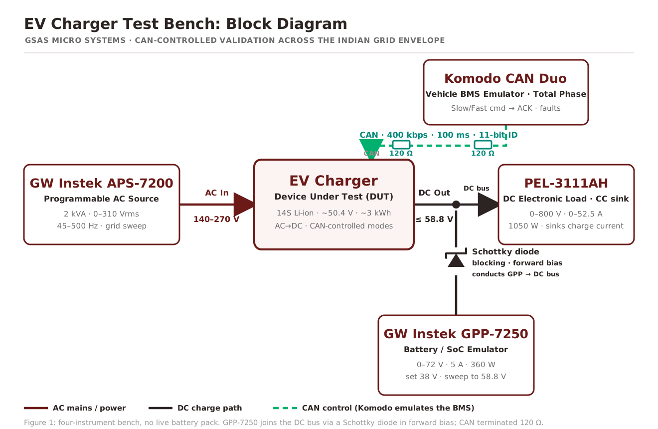
Source, sink, emulate, command: the four roles:
| Block | Instrument | Role on the bench |
|---|---|---|
| AC source | GW Instek APS-7200 | Programmable AC supply; sweeps 140–270 V mains across the full input range |
| DC load | GW Instek PEL-3111AH | DC electronic load (CC sink) emulating the charging current the pack would draw |
| Battery emulator | GW Instek GPP-7250 | Programmable DC supply set to the pack voltage; swept to mimic state of charge |
| Bus isolation | Schottky blocking diode | Prevents reverse current from the charger output back-feeding the emulator |
| CAN control | Total Phase Komodo CAN Duo | Vehicle BMS emulator; commands Slow/Fast modes, reads ACK, current, voltage, faults |
| DUT | AC EV Charger | AC in 140–270 V; DC out up to ~58.8 V; CAN-controlled mode selection |
Bill of materials: what you need to build this bench
Every role on the bench maps to one instrument. Build it with these four programmable units plus one passive part, and you can validate a CAN-controlled EV charger end-to-end with no battery pack and no vehicle.
| Role | What it does | Instrument | Why this one |
|---|---|---|---|
| AC source | Sweeps the mains input across the grid envelope on a script | GW Instek APS-7200 | 2 kVA, 0 to 310 Vrms, 45 to 500 Hz: the 140 to 270 V Indian sweep fits with headroom, and 45 to 500 Hz also covers 50/60 Hz export markets |
| DC load | Sinks the charger’s output current in constant-current mode | GW Instek PEL-3111AH | 0 to 800 V / 0 to 52.5 A / 1050 W: emulates the roughly 3 A Slow and 15 A Fast draw, with room for 48 V/60 V/72 V families up to about 1 kW |
| Battery emulator | Presents the pack voltage and sweeps it through state of charge | GW Instek GPP-7250 | 0 to 72 V / 5 A / 360 W: set to pack voltage and swept 38 V to 58.8 V to mimic a 14S pack filling up in minutes |
| BMS emulator | Speaks the charger’s CAN dialect: commands Slow/Fast, reads ACK and faults | Total Phase Komodo CAN Duo | Two channels with per-channel galvanic isolation, 11-bit and 29-bit IDs, rates up to 1 Mbps: matches the 400 kbps DUT and any common rate |
| Bus isolation | Blocks reverse current from the charger back into the emulator | Schottky blocking diode | Low forward drop passes charge current while reverse-blocking back-feed; easily heatsunk at the 15 A or less handled here |
With the source, sink, emulate and command roles covered, one script drives the four-phase sequence and the bench produces a single compliance report.
Instrument 1: GW Instek APS-7200 programmable AC source
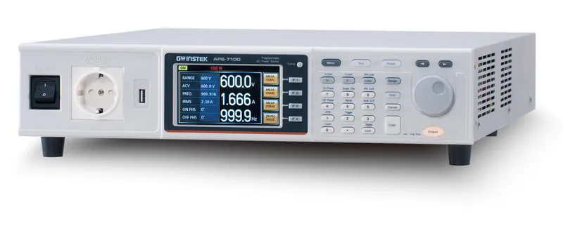
The APS-7200 replaces the variac and the guesswork. It is a GW Instek programmable AC source rated 2 kVA, delivering 0–310 Vrms over 45–500 Hz, so the 140–270 V Indian sweep sits comfortably inside its range with headroom to spare. Under script control it steps the mains in fixed increments and holds each set-point while the rest of the bench logs the charger’s response, and its built-in measurement functions capture input voltage, current, power factor and crest factor without an external analyser.
- Range: 2 kVA, 0 to 310 Vrms, 45 to 500 Hz
- Role on bench: sweeps the 140 to 270 V Indian mains envelope on a script
- Why it matters: the same source covers 50/60 Hz export markets and grid-frequency-variation tests
Because the source is programmable across frequency as well as voltage, the same instrument later covers universal-input chargers for 50/60 Hz export markets and grid-frequency-variation tests, so the bench is not locked to the Indian envelope it was first built for.
Instrument 2: GW Instek PEL-3111AH DC electronic load
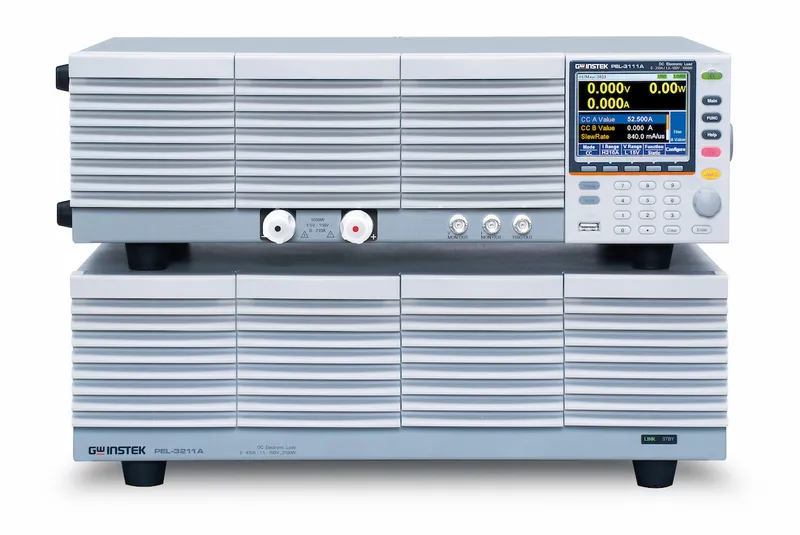
On the output side, the PEL-3111AH is a 0–800 V / 0–52.5 A / 1050 W programmable DC electronic load. Operating as a constant-current (CC) sink, it emulates exactly the current a charging pack would pull, about 3 A in Slow mode and 15 A in Fast mode, so the charger sees a realistic load without a real cell in sight. The load confirms that when the BMS emulator commands a mode, the charger actually delivers the corresponding current, and it can step the load dynamically to probe transient regulation and protection behaviour.
- Range: 0 to 800 V, 0 to 52.5 A, 1050 W
- Role on bench: sinks the charger output as a CC load, verifying the 3 A Slow and 15 A Fast draw
- Why it matters: the 800 V / 1050 W envelope also covers 48 V, 60 V and 72 V light-EV charger families up to roughly 1 kW
As a GW Instek electronic load, the PEL-3111AH is part of the same PEL-3000A programmable DC load family GSAS supplies across India, so a larger charger or battery line scales onto the same control scripts.
Instrument 3: GW Instek GPP-7250 as a battery emulator
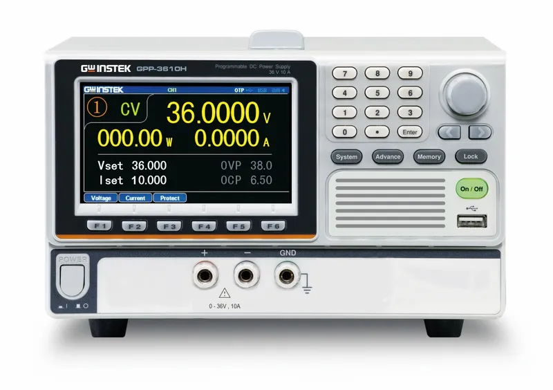
The cleverest substitution on the bench is the GPP-7250, a single-channel 0–72 V / 5 A / 360 W GW Instek programmable DC power supply standing in for the battery pack. Rather than wait hours for a real pack to charge and discharge, the GPP-7250 is set to a chosen pack voltage and swept from 38 V up to 58.8 V to imitate the pack climbing through its state of charge, so the charger’s regulation loop “sees” a battery filling up, in minutes, on a script.
- Range: 0 to 72 V, 5 A, 360 W, single channel
- Role on bench: emulates the pack voltage and sweeps it 38 V to 58.8 V to mimic state of charge
- Why it matters: a full SoC sweep takes minutes, not the hours a real pack needs to charge and discharge
A few volts of arithmetic explain those numbers. A 14S pack stacks 14 cells in series, so the pack voltage is the cell voltage times 14:
- 14 x 3.6 V ≈ 50.4 V nominal
- 14 x 4.2 V ≈ 58.8 V at full charge
- 38 V start ≈ 2.7 V/cell, a deeply discharged (not fully dead) pack
The 50.4 V nominal places this pack in the ~3.6 V/cell class of lithium-ion chemistry (a 14S LFP pack, at ~3.2 V/cell, would sit near 44.8 V nominal instead, so this is not LFP). The exact discharge floor is set by the BMS and varies by cell, typically between 2.5 and 3.0 V/cell.
Why a blocking diode? A Schottky diode sits between the emulator and the charger output. Its low forward drop (typically a few hundred millivolts) passes charge current to the emulated pack while reverse-blocking any back-feed from the charger into the GPP-7250, a classic ORing function. The forward loss is modest and easily heatsunk at the ≤15 A handled here. A higher-current bench would swap it for an active “ideal-diode” stage (a controller-driven MOSFET) that cuts conduction loss to tens of millivolts.
Battery emulator vs programmable DC power supply: when a diode is enough
This bench makes a deliberate, honest tradeoff: it uses a plain GPP-7250 supply plus a Schottky diode instead of a true bidirectional battery emulator. The distinction is worth defining, because it decides what you need to buy.
- A programmable DC power supply only sources current, at near-zero internal impedance. It can hold the pack voltage at any state of charge, which is all a charge-only AC charger ever asks of the pack.
- A true battery emulator both sources and sinks current (four-quadrant operation) and models programmable internal resistance (ESR), so it reproduces how a real pack loads, and is loaded by, the device under test.
For a charge-only AC charger, the pack never needs to push current back, so a source-only supply plus an ORing diode is electrically sufficient and far cheaper. You step up to a four-quadrant emulator when the test demands sink capability or realistic internal resistance: bidirectional onboard chargers, regen and vehicle-to-grid work, or BMS validation that depends on pack impedance. That is the cost-and-capability ladder, and this bench sits deliberately on the lower rung because the DUT does not need the upper one.
Instrument 4: Total Phase Komodo CAN Duo as a BMS emulator
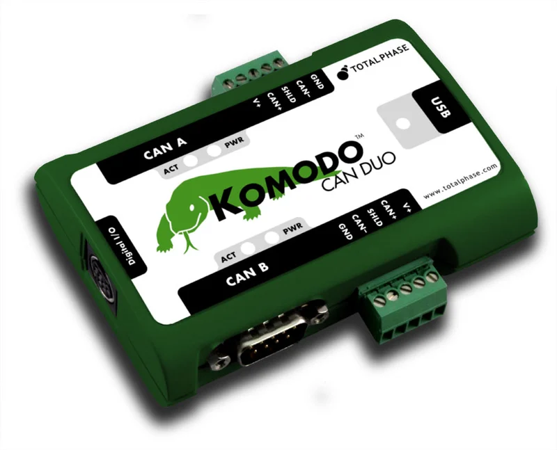
The instrument that makes unattended testing possible is the Komodo CAN Duo. It is a two-channel CAN interface with independent galvanic isolation per channel, support for both standard (11-bit) and extended (29-bit) identifiers, and bit rates up to 1 Mbps. On this bench it becomes the vehicle BMS: it transmits the Slow/Fast mode-command frames and receives the charger’s acknowledgement, current, voltage and fault reports, eliminating the need for a real vehicle BMS and turning the charge handshake into something a script can drive across the entire grid/SoC envelope.
- Channels: two, with independent galvanic isolation per channel
- Role on bench: emulates the vehicle BMS, commanding Slow/Fast and reading ACK, current, voltage and faults
- Why it matters: standard (11-bit) and extended (29-bit) IDs at rates up to 1 Mbps cover any charger CAN profile
For hands-on CAN tooling beyond this bench, see our guides to PicoScope automotive CAN, LIN and FlexRay diagnostics, the SocketCAN guide to CAN bus interfaces, and analysing CAN bus frames and timing with the Komodo CAN Duo.
The CAN communication profile
| Parameter | Value on this bench |
|---|---|
| Bit rate | 400 kbps |
| Bit time | 2.5 µs |
| Frame format | Standard 11-bit identifier; 7-byte data payload (per the DUT protocol) |
| Frame period | 100 ms (10 frames per second) |
| Exchange | Komodo commands Slow/Fast; charger responds with current, voltage, faults |
The bit time follows directly from the rate: a nominal CAN bit time is 1 / bit rate, so 400 kbps gives 2.5 µs/bit (ISO 11898-1; each bit subdivides into integer time quanta for synchronisation). The 100 ms cadence is simply ten frames a second. Note that 400 kbps is a non-standard rate, the common CAN rates are 125, 250, 500 and 1000 kbps, specified here by the DUT and confirmed by a successful charger ACK during testing. The Komodo’s second, isolated channel can passively monitor a live vehicle bus while the first emulates the BMS, which is exactly how you reverse-correlate an unfamiliar protocol on a future DUT.
One detail the block diagram makes explicit: the CAN bus is terminated with a 120 Ω resistor at each physical end (one at the Komodo, one at the charger), per ISO 11898-2. Each 120 Ω resistor matches the twisted-pair characteristic impedance to damp reflections, and the two together present a 60 Ω differential load to the transceivers. Skip them and a 400 kbps bus will throw bit errors and failed ACKs that look like a firmware fault but are really a missing terminator. On the bench the Komodo can supply its own internal termination, and the second resistor sits at the charger end of the harness.
Charger-to-BMS CAN protocols compared: GB/T 27930, SAE J1939, ISO 15118
This bench used a proprietary 400 kbps profile set by the DUT, but engineers benchmark every charger CAN dialect against three reference protocols. Naming them is how you place an unfamiliar profile on the map.
| Protocol | Bit rate | Identifier | Role |
|---|---|---|---|
| GB/T 27930 | 250 kbps | CAN 2.0B (29-bit) | China’s charger-to-BMS handshake standard; defines recognition, configuration, charging and statistics phases |
| SAE J1939 | 250 kbps | 29-bit (PGN/SPN) | Heavy-vehicle CAN standard; the basis of India’s Bharat BEVC charger communication |
| ISO 15118 | High-level comms | n/a (PLC/V2G) | Governs EV-to-EVSE high-level communication, Plug and Charge and vehicle-to-grid; sits above the CAN handshake |
| This DUT | 400 kbps | 11-bit standard | Non-standard rate fixed by the charger; 2.5 microsecond bit time, 100 ms frame period |
A note on scope: the charger-to-BMS CAN handshake described here is distinct from OCPP, which governs charger-to-backend communication, and from ISO 15118, which governs the higher-level EV-to-EVSE conversation. This bench emulates the BMS side of the CAN link only, which is the layer that gates whether the charger delivers current at all.
Methodology: a four-phase automated validation sequence
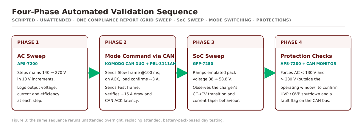
The bench runs one scripted sequence end-to-end, then archives a single report:
- Phase 1, AC sweep. The APS-7200 steps mains from 140 V to 270 V in 10 V increments. At each step, output voltage, current and efficiency are logged.
- Phase 2, mode command via CAN. The Komodo CAN Duo transmits the Slow-charge frame every 100 ms; on the charger’s ACK, the PEL-3111AH confirms the ~3 A draw. The Fast-charge frame is then issued and the ~15 A draw is verified.
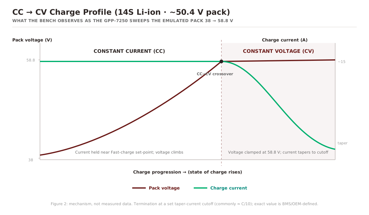
- Phase 3, SoC sweep. The GPP-7250 ramps the emulated pack voltage from 38 V to 58.8 V; the charger’s CC-to-CV transition and current-taper behaviour are observed.
- Phase 4, protection checks. AC input is forced below 130 V and above 280 V to confirm the under-voltage (UVP) and over-voltage (OVP) shutdowns assert, and that a fault flag is raised on the CAN bus.
What CC-to-CV actually means
Phase 3 is where battery-charging physics shows up. Li-ion packs charge in two stages: a constant-current (CC) phase that holds a fixed current while the pack voltage climbs, followed, once the pack reaches its charge-limit voltage near 58.8 V, by a constant-voltage (CV) phase that clamps the voltage and lets the current taper toward a termination cutoff (commonly around C/10, with the exact value set by the BMS/OEM). Sweeping the emulator through that crossover lets the bench watch the charger hand off from current control to voltage control without ever charging a real cell.
The power-quality metrics that matter
While Phase 1 sweeps the mains, the bench characterises three input-side numbers that decide whether a charger is grid-friendly:
- Conversion efficiency: DC output power divided by AC input power; the rest is heat.
- Input-current THD: how much the drawn current departs from a clean sinusoid. Switch-mode front ends without power-factor correction (PFC) pull peaky, harmonic-rich current; IEC 61000-3-2 caps those harmonics for mains-connected equipment.
- Power factor: real power over apparent power. High THD drags PF down even at unity phase, which is why active-PFC designs target PF > 0.9.
EV charger test results: what the bench measured
The measurements below are the results recorded on this bench for this DUT, not universal constants, and every one met or beat the charger’s specification.
| Parameter | Condition | Spec | Measured |
|---|---|---|---|
| Output regulation | AC sweep 140–270 V | ±2% | ±1.4% |
| Conversion efficiency | 230 V AC, Fast mode | ≥ 90% | 92.6% |
| Input current THD | 230 V AC, full load | < 10% | 4.1% |
| Power factor | 230 V AC, full load | > 0.95 | 0.982 |
| CAN ACK latency | Mode cmd to ACK, 400 kbps | < 200 ms | ~110 ms |
| UVP / OVP trip | AC < 130 V / > 280 V | Shutdown + CAN flag | Pass |
Manual versus automated EV charger testing
The same charger can be validated by hand or by script. The difference is repeatability, coverage, and how long an engineer has to stand at the bench.
| Aspect | Manual testing | Automated bench (this build) |
|---|---|---|
| AC input sweep | Variac nudged by hand, set-points approximate | APS-7200 steps 140 V to 270 V in 10 V increments on a script |
| Battery condition | A real 14S pack charged and discharged over hours | GPP-7250 swept 38 V to 58.8 V to emulate state of charge in minutes |
| Charge handshake | Hard to drive without a live vehicle BMS | Komodo CAN Duo commands Slow/Fast at 400 kbps on a 100 ms cadence |
| Protections (UVP/OVP) | Risky to force a real pack to the edges | AC forced below 130 V and above 280 V, CAN fault flag verified |
| Supervision | Attended, daytime only | Unattended, including overnight regression |
| Output | Hand-logged notes, hard to repeat | One automated compliance report covering grid sweep, SoC sweep, mode switching, CAN ACK latency, and protections |
The automated bench is safer (no live pack at the voltage edges), faster (minutes per SoC sweep, not hours), and repeatable: revalidating a different charger needs only new set-points and a new CAN profile, not new hardware.
Extending the bench to other EV chargers
The bench is DUT-agnostic: revalidating a different charger needs only new instrument set-points and a new CAN command profile, with no hardware changes. The APS-7200 (2 kVA, 0–310 Vrms, 45–500 Hz) already covers universal-input chargers and grid-frequency tests beyond the Indian envelope; the PEL-3111AH (0–800 V / 52.5 A / 1050 W) accommodates 48 V/60 V/72 V light-EV charger families up to ~1 kW; and the GPP-7250 emulates pack voltages up to 72 V across their full SoC range. The Komodo CAN Duo’s configurable rates up to 1 Mbps mean chargers on the common 250/500/1000 kbps rates are covered by reloading the frame dictionary alone.
Scaling up, to DC fast chargers and battery-pack lines, is a matter of swapping in higher-power GW Instek instruments while keeping the same architecture: the PEL-5000C high-power DC load (to 192 kW in parallel), the AEL-5000 regenerative AC and DC load, and the ASR-6500 AC/DC power source for grid-tie and bidirectional work. We cover that high-power line in the companion GW Instek 6S high-power test build guide. For the EV-battery side of the same architecture, see our notes on regenerative DC power testing for EV battery validation in India, the GW Instek PEL-5000 high-power DC load, and the GW Instek ASR-6000 SiC AC/DC power source.
Outcomes and value delivered
- A single bench replicates Indian grid edge cases, 140 V brown-out to 270 V over-voltage, without a real battery pack, which is safer and faster than pack-based testing.
- Using the GPP-7250 as a programmable battery emulator allows a full SoC sweep (38 to 58.8 V), exercising CC-to-CV transition and taper logic without waiting for a real pack to charge.
- The Komodo CAN Duo enables scripted mode commands and fault-flag verification at 400 kbps / 100 ms cadence, so unattended overnight regression is possible.
- Automated logging produces one compliance report covering grid sweep, SoC sweep, mode switching, CAN ACK latency and protections, replacing attended, pack-based day testing. For fleet-scale follow-on work, this pairs with EV fleet telematics and battery monitoring in India.
Glossary: EV charger test bench terms
CC-CV charging. The two-stage lithium-ion charge profile: a constant-current (CC) phase holds a fixed current while pack voltage rises, then a constant-voltage (CV) phase clamps the voltage near full charge and lets the current taper toward a termination cutoff (often around C/10).
BMS (Battery Management System). The vehicle electronics that request a charge mode over CAN, monitor pack voltage and current, and enforce safety limits. On this bench the Komodo CAN Duo emulates it.
State of Charge (SoC). How full a battery is, expressed as a voltage on this bench: a 14S pack ranges from about 38 V deeply discharged to 58.8 V at full charge, swept by the GPP-7250 to mimic charging progress.
THD (Total Harmonic Distortion). A measure of how much the charger’s drawn input current departs from a clean sinusoid; lower is better, and IEC 61000-3-2 caps these harmonics for mains-connected equipment. This DUT measured 4.1%.
Power factor (PF). Real power divided by apparent power. High THD drags it down even at unity phase, so active-PFC designs target PF above 0.9. This charger measured 0.982 at 230 V full load.
UVP / OVP. Under-Voltage Protection and Over-Voltage Protection: charger shutdowns that assert when the AC input falls below or rises above safe limits. The bench forced the input below 130 V and above 280 V and confirmed both trip with a CAN fault flag.
Schottky blocking diode. A diode with a low forward drop placed between the battery emulator and the charger output to pass charge current forward while reverse-blocking any back-feed from the charger, an ORing function.
Battery emulator. A programmable DC supply (here the GPP-7250) set to the voltage a real pack would present at a given SoC, used in place of a live battery so the charger can be tested in minutes without a real cell.
DUT (Device Under Test). The item being validated; on this bench it is the AC EV charger, with 140 to 270 V AC in, up to about 58.8 V DC out, and CAN-controlled mode selection.
GW Instek for EV charger and battery test in India
Every programmable instrument on this bench is a GW Instek unit, and that is deliberate. GW Instek builds a single, coherent power-test line that spans the whole EV charger and battery validation problem: programmable AC sources, DC electronic loads and programmable DC power supplies that share one control language, so a four-instrument bench like this scripts as one system rather than four vendors stitched together.
For an Indian EV or charger OEM, the practical questions are availability, currency and support, not just datasheet numbers. GSAS Micro Systems is an authorized GW Instek engineering partner for Karnataka, Andhra Pradesh and Telangana, supporting customers across India: we supply the full GW Instek power-test range with INR invoicing and GeM registration, and we back it with local calibration and applications support in Bengaluru, Hyderabad, Chennai, Pune, Mumbai and Delhi NCR. That means the GW Instek APS-7200 AC source, PEL-3111AH electronic load and GPP-7250 DC power supply used here are not import-only line items, they are stocked, quoted in rupees and supported by engineers who have built the bench.
The same GW Instek line scales in both directions. Below this two-wheeler charger bench sit bench-grade GW Instek programmable DC power supplies and the PEL-3000A electronic load family. Above it sit the PEL-5000C high-power DC load, the AEL-5000 regenerative AC and DC load and the ASR-6500 AC and DC power source for DC fast chargers and battery-pack lines, plus the GW Instek DAQ-9600 data acquisition system for multi-channel temperature and voltage logging across a pack. We map the whole range in the GW Instek 6S high-power test catalog for India.
Why GSAS for EV charger test in India
For an OEM scoping an EV charger test bench in India, no single instrument vendor ships this off the shelf, and the value is in the integration: choosing the right source, sink, emulator and CAN tool, wiring the bus isolation, and scripting the four-phase sequence into one repeatable campaign. As an engineering partner for GW Instek and Total Phase, GSAS designs, integrates and supports test benches like this one across Bengaluru, Hyderabad, Chennai, Pune, Mumbai and Delhi NCR, with INR invoicing, GeM registration and local calibration and applications support. It pairs with our testing and validation, test and measurement and CAN/LIN testing capabilities, and our EV and energy and two-wheeler EV solution practices.
📄 Download the full case study (PDF) · Request a quote · Book a demo · Talk to GSAS
Frequently asked questions
What instruments do you need to build an EV charger test bench?
At minimum: a programmable AC source to sweep the mains input, a DC electronic load to sink the charger’s output current, a programmable DC supply to emulate the battery pack’s state-of-charge voltage, and a CAN interface to emulate the vehicle BMS handshake. This bench used a GW Instek APS-7200, PEL-3111AH and GPP-7250 with a Total Phase Komodo CAN Duo, plus a Schottky blocking diode for bus isolation.
How do you test an EV charger across the Indian grid voltage range?
With a programmable AC source commanded across the full input window, here 140 to 270 V in 10 V steps, rather than a manual variac. India’s nominal supply is 230 V at about plus or minus 6 percent (CEA 2010 / IEC 60038), but a robust charger is tested well below and above that band to cover brown-out and over-voltage, with output regulation logged at every step.
What is a battery emulator and why is it needed for EV charger testing?
In its simplest bench sense, a battery emulator is a programmable DC supply set to the voltage a real pack would present at a given state of charge. Sweeping it (here 38 to 58.8 V for a 14S pack) lets the charger’s regulation loop see a filling battery in minutes, exercising the constant-current to constant-voltage transition without the time, bulk or hazard of charging a real pack.
How does a CAN bus BMS emulator validate a charger handshake?
The emulator transmits the same CAN frames a vehicle BMS would, mode commands on a fixed cadence, and reads back the charger’s acknowledgements, current, voltage and fault reports. That lets an automated script drive the full Slow/Fast negotiation and inject faults, so the charger is tested as it behaves in a vehicle, not just at idle.
Can the same bench test a DC fast charger, or only a two-wheeler charger?
The architecture scales. The same source, sink, emulate and command pattern carries up to DC fast chargers and battery lines by swapping in higher-power GW Instek instruments, for example the PEL-5000C DC load, AEL-5000 regenerative load and ASR-6500 AC/DC source, while keeping the CAN-emulation and scripting layer unchanged.
What is the difference between a battery emulator and a programmable DC power supply?
A plain programmable DC supply only sources current at near-zero internal impedance. A true battery emulator both sources and sinks current and models programmable internal resistance and state-of-charge behaviour, so it reproduces how a real pack loads a charger. This charge-only AC charger bench deliberately uses a source-only GPP-7250 supply plus a Schottky blocking diode instead of a four-quadrant emulator, because the charger never needs the pack to sink current. Bidirectional or regen testing is where a full source-and-sink emulator earns its cost.
What CAN bit rate do EV chargers use?
It depends on the charger’s protocol. The common standard CAN rates are 125, 250, 500 and 1000 kbps. Under China’s GB/T 27930 charger-to-BMS standard the rate is 250 kbps on CAN 2.0B. This DUT specified a non-standard 400 kbps (2.5 microsecond bit time, 11-bit identifiers, 100 ms frame period), confirmed by a successful charger ACK during testing. The Komodo CAN Duo supports rates up to 1 Mbps, so it can match whichever rate a charger requires.
What standards apply to EV charger testing in India?
For AC conductive charging, AIS-138 Part 1 (issued by ARAI) sets India’s requirements and derives from IEC 61851, alongside the IS 17017 series of Indian EVSE standards and the legacy Bharat AC-001 specification. IEC 60038 and the CEA Regulations 2010 define the 230 V supply that the 140 to 270 V grid sweep brackets, IEC 61000-3-2 caps input-current harmonics (which is why THD and power factor are measured), and the CAN data link follows ISO 11898-1. Certification is carried out by ARAI, ICAT, CPRI or another NABL-accredited lab.
Is GW Instek good for EV charger and battery testing?
Yes. GW Instek’s power-test line covers the full EV charger and battery validation chain in one ecosystem: programmable AC sources for the grid input, DC electronic loads to sink charger and pack current, and programmable DC power supplies that stand in as battery emulators. This bench used the GW Instek APS-7200, PEL-3111AH and GPP-7250 together, and the same line scales up to the PEL-5000C, AEL-5000 and ASR-6500 for DC fast chargers and battery-pack lines.
Where can I buy GW Instek and Total Phase test instruments in India?
GSAS Micro Systems is an engineering partner for both GW Instek and Total Phase in India, supplying and integrating these instruments with INR invoicing, GeM registration and local calibration and applications support. Request a quote or talk to GSAS.
References
- AIS-138 (Part 1): Electric Vehicle Conductive AC Charging System requirements (ARAI), aligned with IEC 61851.
- IS 17017 series: Electric Vehicle Conductive Charging System (BIS); Bharat AC-001 (Bharat EV Charger AC specification).
- IEC 60038: IEC Standard Voltages (230/400 V, 50 Hz). CEA (Measures Relating to Safety and Electric Supply) Regulations, 2010; IS 12360: Voltage Bands for Electrical Installations.
- ISO 11898-1: Road vehicles, Controller Area Network (CAN), data link layer and physical signalling. GB/T 27930 (charger-to-BMS communication); SAE J1939; ISO 15118 (V2G / Plug and Charge).
- IEC 61000-3-2: Limits for harmonic current emissions (equipment input current up to 16 A per phase).
- GW Instek product documentation: APS-7000 series, PEL-3000A/AH series, GPP-3610H/7250. Total Phase: Komodo CAN Duo interface datasheet.
Also appears in:
Interested in GW Instek tools?
Talk to our application engineers for personalized tool recommendations.
More from GW Instek
View all →
Emulating Processor Power for Thermal Testing: Why Constant Power
7 Oct · 7 min

CRPS and Rack Power Supply Testing: The Six Tests That Matter
7 Oct · 7 min

GPU Power Board Testing: DC Input Verification Before Integration
7 Oct · 6 min
Servo Motor Inrush Current Testing: Method, Limits and Bench
7 Oct · 6 min

SuperTest Van Gogh 6.0: C23, C++23 and the C++20 Modules Gap
6 Oct · 7 min

AI Inside the Engineering Process: What Is Worth Automating, and What Still Needs an Engineer
21 Sept · 11 min