
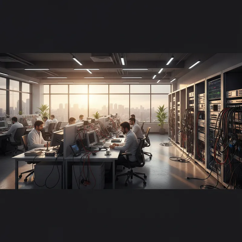
Why Automotive Engineers Need Oscilloscopes
Modern vehicles contain 30–100+ electronic control units (ECUs) communicating over multiple bus networks, CAN, CAN FD, LIN, FlexRay, and increasingly Automotive Ethernet. When a vehicle exhibits an intermittent fault, a sensor dropout, a communication glitch, an actuator that misbehaves under specific conditions, diagnostic scan tools can read fault codes, but they cannot show you what is happening at the electrical level.
An oscilloscope reveals the physical reality of the signals: voltage levels, rise times, bus termination quality, noise, reflections, and timing. For automotive R&D engineers, test engineers, and advanced diagnostic workshops, this visibility is essential.
PicoScope Automotive Advantages
Pico Technology has a deep history in automotive measurement, their automotive division produces purpose-designed kits and software features for vehicle diagnostics. PicoScope oscilloscopes offer several advantages for this application:
Protocol Decoding: Included Free
PicoScope 7 software includes protocol decoders for:
- CAN and CAN FD: standard and flexible data rate
- LIN: Local Interconnect Network
- FlexRay: time-triggered, deterministic bus
- I2C, SPI, UART: for sensor and module-level debugging
- Sent (SAE J2716): single-edge nibble transmission for sensors
These decoders are included free with every PicoScope, no per-protocol license fees. Compare this to traditional benchtop oscilloscopes where protocol decoders can cost Rs 50,000–1,50,000 per protocol.
Deep Memory for Bus Capture
Automotive bus communication is continuous. A CAN bus at 500 kbit/s generates thousands of frames per second. To capture meaningful sequences, complete diagnostic sessions, state transitions, or rare error events, you need deep memory.
The PicoScope 6000E provides up to 4 GS of buffer memory, allowing extended bus captures at full sample rate. Lower-tier models like the PicoScope 3406E and PicoScope 5000D also provide generous buffers for bus analysis.
Portability
PicoScope oscilloscopes are USB-powered and laptop-sized. An automotive engineer can carry the scope, probes, and a laptop to the vehicle, in the parking lot, on the production line, or at a customer site. No benchtop instrument, power cord, or cart required.
Practical Application: CAN Bus Analysis
Physical Layer Diagnostics
Before decoding protocol content, verify the physical layer:
-
Differential voltage: CAN_H and CAN_L should show differential voltage swings of approximately 2V (dominant) and 0V (recessive). Measure both CAN_H-to-GND and CAN_L-to-GND to verify symmetry.
-
Bus termination: A properly terminated CAN bus shows clean signal edges with minimal ringing. Unterminated or improperly terminated buses show oscillations after each transition, visible immediately on the oscilloscope.
-
Rise/fall times: CAN transceiver specifications define acceptable rise and fall times. Measuring these confirms transceiver health and cable quality.
-
Common-mode voltage: Both CAN_H and CAN_L should idle at approximately 2.5V. Deviations indicate ground offset or bus fault conditions.
Protocol-Level Analysis
With physical layer integrity confirmed, enable the CAN decoder in PicoScope 7:
- View decoded message IDs, data bytes, and DLC alongside the raw waveform
- Filter specific message IDs to isolate communication between specific ECUs
- Identify error frames, CAN error flags indicate bus errors that may correspond to the intermittent fault
- Measure message timing to verify that periodic messages arrive at expected intervals
Intermittent Fault Capture
For faults that occur sporadically, configure PicoScope in single-trigger mode with a trigger condition on the CAN bus error flag or an abnormal voltage level. The deep memory captures the events surrounding the fault, providing context for root cause analysis.
LIN Bus Diagnostics
LIN (Local Interconnect Network) connects lower-speed peripherals, window motors, seat controls, rain sensors, mirror adjusters. LIN operates at 19.2 kbit/s or lower, making it straightforward to capture and decode with any PicoScope model.
Common LIN faults visible on the oscilloscope:
- Missing response: The master sends a header, but no slave responds, visible as a header frame followed by idle bus instead of the expected data frame
- Voltage level issues: LIN uses a single wire with voltage levels referenced to battery voltage. Weak pull-up, corroded connectors, or voltage drops along the harness are visible as reduced swing or slow edges
- Timing violations: Slave response timing outside specification
FlexRay Diagnostics
FlexRay is used in safety-critical chassis and powertrain systems (predominantly in European vehicles). Its time-triggered architecture requires precise timing analysis that only an oscilloscope can provide.
PicoScope’s FlexRay decoder displays slot assignments, cycle structure, and payload data alongside the physical waveform, enabling both protocol and physical layer diagnosis in a single view.
Why Buy PicoScope for Automotive from GSAS
GSAS Micro Systems is an authorized Pico Technology partner. Our automotive application engineers support workshops and R&D teams across India with scope selection, probe configuration, and measurement technique training.
- Automotive probe kits: breakout leads, back-probing pins, and CAN/LIN bus tap accessories
- Training workshops: CAN/CAN FD/LIN decode, sensor diagnostics, NVH measurement
- INR invoicing with GST-compliant documentation
- Demo units at offices in Bengaluru, Hyderabad, Chennai, Pune, Mumbai, and Delhi NCR
Also appears in:
Interested in Pico Technology tools?
Talk to our application engineers for personalized tool recommendations.
More from Pico Technology
View all →
How to Buy an Oscilloscope in India (2026): USB vs Benchtop, Bit Depth, Bandwidth: A Buying Guide
5 Jun · 11 min
PicoScope 5000D vs 5000E: Native 16-Bit or FlexRes? A Buyer's Guide for Indian Labs
4 Jun · 11 min
PicoScope 5000E in India: The World's First 4-Channel 16-Bit USB Oscilloscope, Explained
4 Jun · 11 min
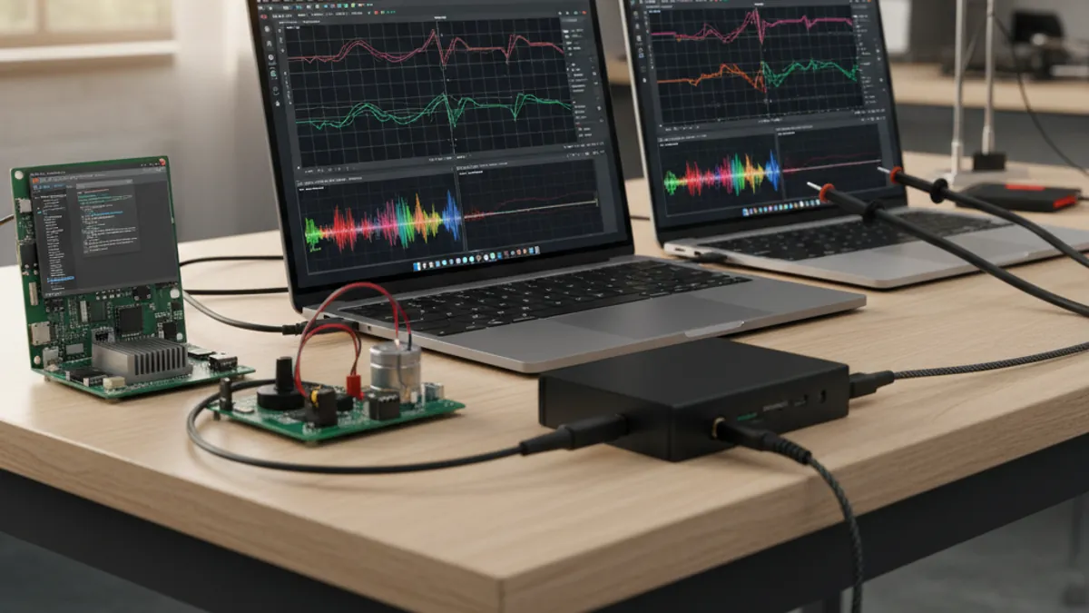
PicoScope 7 Goes Native Arm64: Apple Silicon, Snapdragon Windows and Arm Linux Test Benches in India
4 Jun · 11 min

Emulating Processor Power for Thermal Testing: Why Constant Power
7 Oct · 7 min

CRPS and Rack Power Supply Testing: The Six Tests That Matter
7 Oct · 7 min


