Capabilities · CAN and LIN

CAN and LIN networks, tested from the wire up.

Capture and decode on CAN and CAN FD, physical-layer validation on the differential pair, LIN schedule checks, scripted bench stimulus and fleet data pipelines, for ECU, EV and telematics teams in India.

  1. 01 What we do
  2. 02 Inside a frame
  3. 04 Where to start
01

Five places on the bus where GSAS does the work.

From the differential pair to the fleet portal. Each card lights the point on the vehicle's networks where that work happens.

  • Where GSAS works on the bus
A vehicle's CAN FD, CAN and LIN networks as a schematic, with the five CAN and LIN disciplines GSAS covers numbered as on the cards Powertrain · CAN FD Engine Inverter BMS Gateway OBD-II Body · CAN Body Cluster Door 2× CAN Bench ECU · script LIN Window Mirror Seat 1. Interface on the body CAN: capture and decode 1 2. Scope on the powertrain CAN FD pair: physical layer 2 3. LIN cluster behind the door module: LIN analysis 3 4. Bench ECU with scripted traffic: stimulus and regression 4 5. OBD-II port and telematics unit: fleet data 5
  • 1. Interface on the body CAN: capture and decode
  • 2. Scope on the powertrain CAN FD pair: physical layer
  • 3. LIN cluster behind the door module: LIN analysis
  • 4. Bench ECU with scripted traffic: stimulus and regression
  • 5. OBD-II port and telematics unit: fleet data
Hover, tap or focus a numbered point or a card to see where each capability sits.
  1. Capture

    CAN and CAN FD capture and decode

    Every bus debug starts with the same question: what is actually on the bus? Capture it, decode it, and turn raw IDs into signals an engineer can read.

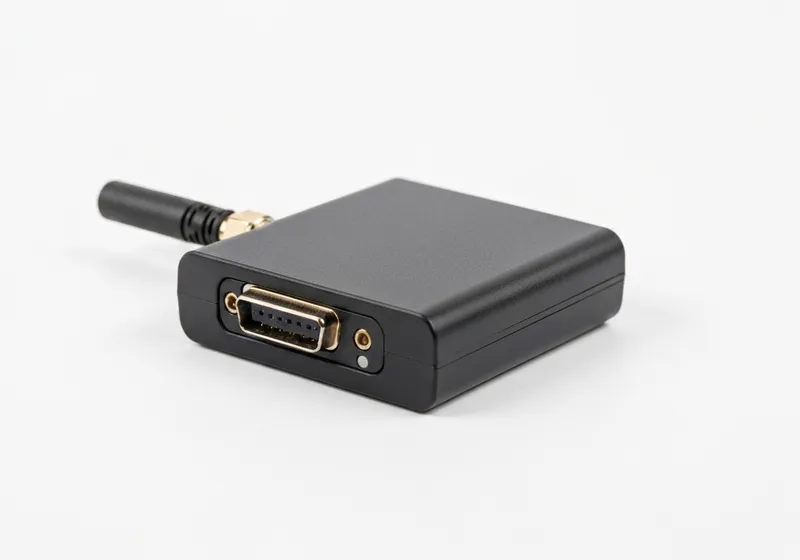
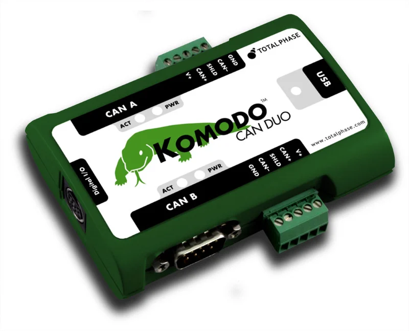
    • Two isolated CAN channels, active or listen-only, on the Komodo CAN Duo
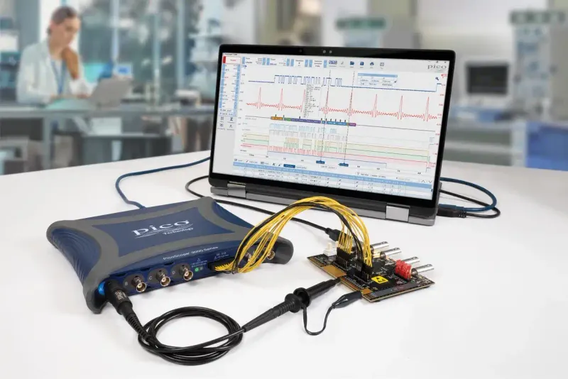
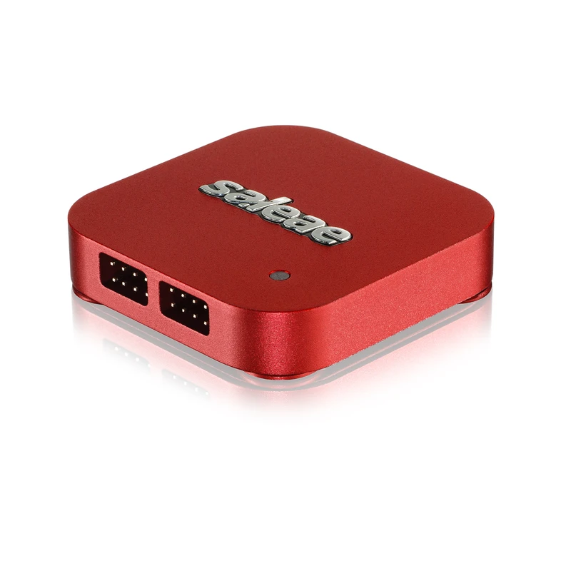
    • CAN FD captured with PicoScope and Saleae decoders, or logged in-vehicle
    • J1939, ISO-TP, UDS and OBD-II interpretation; DBC-driven signals
    • Bus-off, arbitration loss and bit, stuff and form errors logged per channel

    Bench: Komodo CAN Duo · PicoScope · Saleae
  2. Physical layer

    CAN physical-layer validation

    Protocol tools cannot see a weak dominant level, a wrong sample point or a missing terminator. A scope on CAN_H and CAN_L can.

    • Differential levels and margins against ISO 11898-2
    • Bit timing and sample point, including the CAN FD data phase
    • Termination and topology: two 120 Ω ends read 60 Ω across the bus
    • Serial decode over the analogue capture, so a glitch has a frame

    Bench: PicoScope 3403D MSO

  3. LIN

    LIN analysis for body electronics

    Seat motors, window lifters, mirrors and HVAC flaps still run on LIN. When a node misses its slot, the schedule tells you why.

    • LIN 2.x and SAE J2602 frame decode: break, sync, PID, data, checksum
    • Schedule-table and slave response-time checks against the LDF
    • NAD and node configuration verification
    • CAN-to-LIN gateway behaviour, both sides captured together

    Bench: PicoScope · Saleae (controller side of the transceiver)

  4. Stimulus

    Bench stimulus and regression

    Watching traffic is half the job. An ECU on the bench needs the rest of the vehicle played to it, the same way every time.

    • Scripted transmit sequences through the Komodo C, C++, Python and .NET APIs
    • Error behaviour observed and logged as the ECU recovers
    • Regression captures run from CI against the same sequences
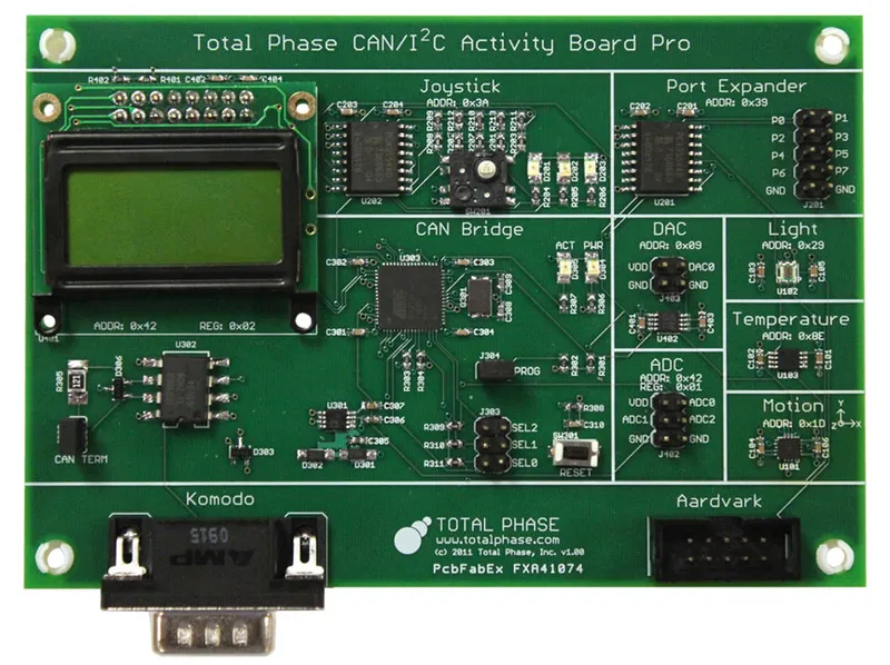
    • Known CAN and I2C target nodes for bring-up and training benches

    Bench: Komodo CAN Duo · CAN/I2C Activity Board Pro

  5. Fleet

    Fleet and telematics CAN data

    For fleets, EV programmes and vehicle data logging, the bus has to be read in the field and the data moved somewhere useful.

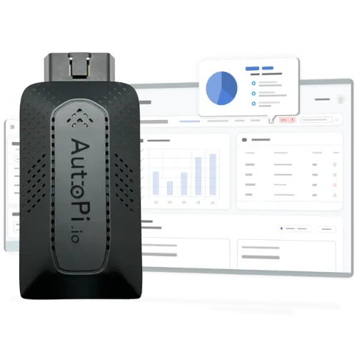
    • In-vehicle logging on two CAN FD channels, up to 5 Mbps
    • OBD-II and J1939 data pipelines to cloud and fleet platforms
    • Edge processing in Docker on the telematics unit
    • Battery-management and powertrain data captured for analysis

    Bench: AutoPi CAN-FD Pro · AutoPi TMU CM4

02

Three stages, from the voltage on the wire to the signal in the DBC.

A bus fault lives at one of three depths. Hover a stage to see which fields of a CAN FD frame and a LIN frame it checks.

Physical · Frame · Message
CAN FD frame: start of frame, arbitration ID, control, data, CRC, acknowledge and end of frame, with the data phase at the faster bit rate. LIN frame: break, sync, protected ID, data and checksum. CAN FD Arbitration phase · nominal bit rate Data phase · faster bit rate (BRS) SOF 1 bit Arbitration ID 11 or 29 bit Control FDF · BRS · DLC Data 0 to 64 bytes CRC 17 or 21 bit ACK EOF 7 bits LIN Header · master Response · slave Break ≥13 bits low Sync 0x55 PID ID + parity Data 1 to 8 bytes Checksum
  1. 01

    Physical

    Levels
    dominant and recessive margins
    Timing
    bit time and sample point
    Topology
    termination, stubs, ringing
    LIN
    break and sync field timing
    Physical-layer validation
  2. 02

    Frame

    Arbitration
    IDs, priority, arbitration loss
    Control
    DLC, FDF and BRS bits on CAN FD
    Integrity
    CRC, stuff and form errors
    LIN
    protected ID and checksum
    Capture and decode
  3. 03

    Message

    Signals
    DBC and LDF decoded values
    J1939
    PGNs and multi-packet transport
    Diagnostics
    ISO-TP segmentation and UDS
    Schedules
    LIN slots and response times
    Stimulus and regression
03

The tools behind the work.

Partner lines GSAS carries, with application engineering, INR invoicing and on-site set-up. Figures are the OEM's own, as published on each product page.

Related: Automotive Ethernet · Functional safety · Total Phase · AutoPi · Pico Technology

04

Three ways in, depending on where the work is.

Most teams arrive with one of these. Pick the one closest to yours.

  1. 01

    Equip a bench

    New ECU or a new team

    Pick the interfaces and scopes the bench actually needs, set them up, and get the team decoding real traffic in the first session.

    • Interfaces sized to the buses on the ECU
    • DBC and LDF decoding set up
    • Supplied in India with INR invoicing
  2. 02

    Debug a bus

    Errors, bus-off, missing frames

    Work the fault from the wire up: levels and timing on a scope, then frames, then signals, until the symptom has a cause.

    • Scope and decode on the same capture
    • Error counters read per channel
    • CAN-to-LIN gateways checked both sides
  3. 03

    Build a data pipeline

    Fleets, EVs, data logging

    Read the bus in the field, process it at the edge, and land it in the platform the fleet already uses.

    • CAN FD and OBD-II logging units
    • J1939 to fleet portal
    • Edge processing in Docker
05

A bus that will not behave?

Tell us the ECU, the bus and the symptom. GSAS engineers reply from India with how they would capture it, what they would measure, and the tooling it needs.

sales@gsasindia.com +91 80 6590 1783

CAN and LIN bus testing with GSAS in India

Does the Komodo CAN Duo support CAN FD?

No. The Komodo CAN Duo is a two-channel, galvanically isolated classic CAN interface, up to 1 Mbps per channel. For CAN FD, GSAS uses PicoScope and Saleae serial decoding on the bench, and the AutoPi CAN-FD Pro (two CAN FD channels, up to 5 Mbps) for in-vehicle logging.

Can a logic analyser probe the CAN bus directly?

Not the differential pair. Saleae inputs are single-ended, so probe the CAN RX and TX lines between the transceiver and the microcontroller. For the bus itself, use an oscilloscope on CAN_H and CAN_L.

Where should I probe a 12 V LIN bus?

On the controller side of the LIN transceiver, where the signal is at logic level. The raw LIN line runs at battery voltage, beyond what a logic analyser input accepts; an oscilloscope can measure the bus line itself.

How do I check CAN termination?

With the bus powered down, measure across CAN_H and CAN_L. Two 120 Ω terminators in parallel read about 60 Ω. A reading near 120 Ω means one is missing; much lower means an extra one. A scope then shows whether the edges ring.

Which protocols does GSAS decode on CAN?

J1939, ISO-TP, UDS and OBD-II, plus application signals from your DBC file. On LIN, frames are decoded against the LDF, with schedule and response-time checks.

Where does GSAS support CAN and LIN work in India?

Engineering is led from Bengaluru, with offices in Chennai, Pune, Hyderabad, Mumbai and Delhi NCR among others, so support runs in Indian working hours.