
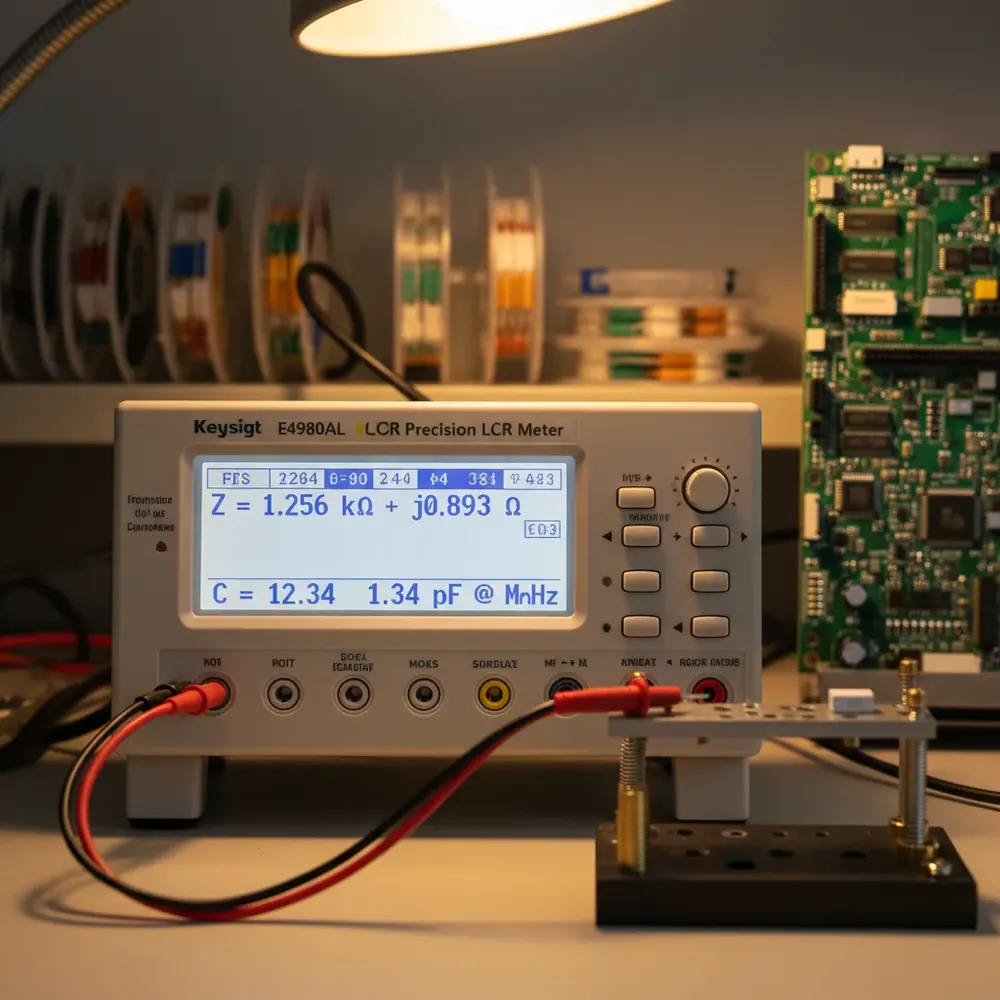
Every passive component that enters an electronics assembly, every capacitor, inductor, and resistor, has an impedance that varies with frequency, temperature, and applied voltage. An LCR meter is the instrument that quantifies this impedance, breaking it down into its fundamental constituents so engineers and quality teams can verify that components meet their specifications before they reach a solder joint. Understanding what an LCR meter actually measures, and how its specifications affect measurement quality, is essential for anyone selecting an instrument or interpreting its readings.
This guide walks through the core measurement parameters, explains why test frequency matters more than most engineers realize, and covers the practical specifications that determine whether an LCR meter is suitable for a given application, from incoming component inspection to production-line bin sorting.
What an LCR Meter Actually Measures
The name “LCR” refers to the three primary passive component types, inductance (L), capacitance (C), and resistance (R), but a modern LCR meter measures far more than these three quantities. At its core, the instrument applies a small AC test signal to the device under test and measures the resulting complex impedance. From this single complex measurement, the instrument derives a family of related parameters.
Impedance (Z) is the total opposition to alternating current, expressed as a complex number with a real (resistive) and imaginary (reactive) component. The magnitude |Z| and phase angle theta together fully describe how a component responds to an AC signal at a given frequency. Inductance (L) and capacitance (C) are derived from the reactive component of impedance. The instrument applies the appropriate formula based on whether the reactance is inductive (positive) or capacitive (negative), and whether the operator selects a series or parallel equivalent circuit model. Resistance (R) represents the real component of impedance, the energy-dissipating element. For capacitors, the series resistance is called ESR (equivalent series resistance), a critical parameter for power supply decoupling and filtering applications. Dissipation factor (D) quantifies the ratio of energy lost to energy stored per cycle. For capacitors, a lower D indicates a better dielectric, essential for timing circuits, filters, and audio applications. Quality factor (Q) is the reciprocal of D and is the preferred figure of merit for inductors and resonant circuits, where higher Q means sharper selectivity and lower loss. Phase angle (theta) directly indicates how close a component is to ideal behavior. A perfect capacitor has a phase angle of -90 degrees; a perfect inductor has +90 degrees. Deviations from these ideals indicate resistive losses.
The Microtest 6360, 6621, and 6630 series LCR meters measure Z, L, C, R, D, Q, ESR, DCR, and theta, along with admittance (Y), reactance (X), conductance (G), and susceptance (B). The 6630 series and the 6632 impedance analyzers add the material parameters, permittivity (epsilon-r) and permeability (mu-r). Understanding which parameters matter for a specific component type is the first step in configuring an effective test.
Why Test Frequency Is Not Optional
A capacitor’s impedance is not a fixed number. A 100 nF ceramic capacitor measured at 1 kHz will show a different capacitance value than the same component measured at 100 kHz or 1 MHz. This frequency dependence is not a measurement error, it reflects the real physics of dielectric behavior, parasitic inductance, and series resistance.
For meaningful measurements, the test frequency should match the component’s actual operating frequency. An electrolytic capacitor used for bulk filtering in a 50 Hz rectifier circuit should be measured at 120 Hz (the ripple frequency). A ceramic decoupling capacitor in a 1 MHz switching converter should be characterized at 1 MHz or higher, where its ESR and parasitic inductance dominate its behavior.
The Microtest LCR meter lineup spans this range: the 6360 series covers 1 mHz to 1 MHz across five models (6363 through 6367), the 6621 series runs from 10 Hz to 30 MHz, and the 6630 series pushes to 50 MHz for high-frequency component analysis. Selecting a meter whose frequency range covers the actual operating frequency of the components being tested is the single most important specification decision.
Accuracy Grades and What They Mean
LCR meter accuracy is typically expressed as a basic accuracy percentage, for example, 0.05%, which represents the best-case measurement uncertainty under optimal conditions (typically at 1 kHz with a medium-impedance DUT). Real-world accuracy degrades from this basic figure as conditions deviate from the optimum: lower or higher test frequencies, very low or very high impedance values, faster measurement speeds, and non-ideal fixture configurations all increase measurement uncertainty.
The Microtest 6360 series specifies 0.05% basic accuracy, and the 6621 and 6630 series specify a typical 0.05%. This level of accuracy is sufficient for the vast majority of component testing applications, including incoming inspection, production sorting, and engineering characterization. The critical consideration is not just the basic accuracy figure but the accuracy at the specific test frequency and impedance range relevant to the application.
For production environments, accuracy must be evaluated against the tightest tolerance grade being sorted. If the production line needs to sort 1% resistors into pass and fail bins, a 0.05% basic accuracy meter provides a 20:1 test uncertainty ratio (TUR) at the optimal measurement point, comfortably exceeding the 4:1 minimum TUR recommended by metrology standards.
Measurement Speed vs. Accuracy Tradeoffs
Every LCR measurement involves applying a test signal, waiting for the DUT response to stabilize, digitizing the result, and computing the impedance. Faster measurements use shorter integration times, which increases measurement noise and reduces accuracy. Slower measurements average more cycles, improving noise rejection and accuracy at the cost of throughput.
The Microtest 6360 series measures in as little as 8 ms, while the 6621 and 6630 series reach under 3 ms per measurement, significantly faster for high-throughput production testing. In production environments, the correct speed setting balances throughput against the accuracy needed for the tolerance grades being sorted. A line sorting 5% tolerance capacitors can use maximum speed; a line sorting 0.1% precision resistors needs the slower, more accurate mode.
DC Bias for Inductor Testing
Inductors used in switch-mode power supplies carry significant DC current during operation, and their inductance decreases as the core material saturates. An inductor rated at 10 uH at zero current might drop to 5 uH or less at its rated operating current. Measuring inductance without DC bias produces a number that has no relationship to the component’s actual performance in circuit.
The Microtest DC bias current sources, from the 20 A 6225 up to the 640 A 6243H, pair with the LCR meters and impedance analyzers to superimpose a programmable DC bias current onto the AC measurement signal. This enables measurement of inductance versus DC bias current, the fundamental saturation curve that power electronics designers need. Automated sweep modes step through programmed DC current values, generating complete L-versus-IDC curves for evaluating saturation onset, knee current, and rated-current inductance.
For Indian power electronics manufacturers designing converters for EV chargers, telecom rectifiers, and industrial drives, DC bias testing is not optional, it is the difference between selecting a component from a datasheet and validating that the component will actually work in the application.
4-Terminal Kelvin Connections
When measuring low-impedance components, milliohm-range ESR, low-value resistors, or inductor DCR, the resistance of the test leads and fixture contacts becomes significant relative to the DUT impedance. In a 2-terminal connection, the instrument measures the total loop resistance including leads and contacts, not just the DUT.
The 4-terminal Kelvin connection solves this by using separate pairs of wires for current injection and voltage sensing. The current-carrying leads can have any reasonable resistance without affecting the measurement, because the voltage sense leads carry negligible current and therefore drop negligible voltage. This technique is used across the entire Microtest LCR meter range and is non-negotiable for accurate measurement of components below approximately 10 ohms.
In production environments where test fixture contacts wear over thousands of insertion cycles, the Kelvin technique maintains measurement integrity regardless of contact condition, a critical advantage for high-volume testing operations.
Bin Sorting for Production
Production-line component testing is not just about measuring values, it is about classifying components into tolerance grades and routing them to the correct output. Bin sorting automates this process: the LCR meter measures the component, compares the result against programmed limits, and outputs a bin assignment to a handler or sorting mechanism.
A typical bin sorting setup might classify capacitors into five bins: below tolerance (reject), low-side acceptable, nominal, high-side acceptable, and above tolerance (reject). The Microtest 6360, 6621, and 6630 series all support multi-bin classification with handler interfaces, enabling integration with automated component feeding and sorting systems for reel-to-reel, tray-based, and tube-based testing workflows.
Combined with barcode-triggered test program selection, a single test station can handle multiple component types in mixed-model production, switching test parameters and bin limits automatically based on the scanned part number.
Selecting the Right LCR Meter
The selection decision comes down to three primary factors: maximum test frequency (which determines the component types and applications the meter can address), measurement speed (which determines production throughput), and automation features (handler interfaces, bin sorting, barcode triggering) that determine how the meter integrates into the production workflow.
For standard incoming QC of electrolytic capacitors and general passive components, the Microtest 6360 series provides the essential capability at a cost-effective price point. For broader frequency coverage into the MHz range, the 6621 series extends the measurement range to 30 MHz. For high-frequency characterization up to 50 MHz with maximum production speed, the 6630 series is the instrument of choice.
Get LCR Meter Guidance from GSAS India
GSAS Micro Systems is an authorized Microtest partner in India, supporting component manufacturers, incoming inspection operations, and contract electronics assemblers. Our applications engineering team provides LCR meter model selection guidance based on your specific component types, tolerance grades, and throughput requirements. We support test sequence programming, fixture design, handler interface configuration, and calibration coordination, everything needed to deploy Microtest LCR meters into Indian production environments.
Contact us from any of our 11 offices in nine Indian cities, including Bengaluru, Chennai, Hyderabad, Delhi NCR, Mumbai, and Pune, for INR pricing, demo instrument availability, and application consultation.
Also appears in:
Interested in Microtest tools?
Talk to our application engineers for personalized tool recommendations.
More from Microtest
View all →
Power Measurement for Server PSUs: Microtest 7140 Power Analyzer
7 Apr · 5 min

Wireless Charger QC Testing with the Microtest 9901
7 Apr · 5 min
Motor Stator Testing in EV Manufacturing: Microtest MT-6910 Series
7 Apr · 5 min
PCB Incoming Inspection with Multichannel LCR Testing
6 Apr · 5 min

Emulating Processor Power for Thermal Testing: Why Constant Power
7 Oct · 7 min

CRPS and Rack Power Supply Testing: The Six Tests That Matter
7 Oct · 7 min

