
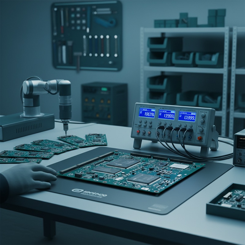
A populated PCB might carry fifty or more passive components, inductors, capacitors, resistors, each specified to tolerances that the assembled circuit depends on. A wrong-value component, an open solder joint on a passive, or a degraded capacitor that passed the component manufacturer’s outgoing test but failed during reflow, any of these defects can cause a board to malfunction in ways that functional testing alone may not isolate efficiently.
Multichannel LCR testing addresses this by measuring passive component values directly on the populated board, across all test points simultaneously, before the board proceeds to functional test. It is incoming inspection and post-reflow verification combined, at production speed.
The Microtest 9332 Series
The Microtest 9332 multichannel LCR meter provides 20 to 48 test channels, each capable of independent passive component measurement. The system contacts the PCB through a bed-of-nails or spring-probe fixture and measures L, C, R, Z, D, Q, and ESR at each test point in a single automated cycle.
Test frequency: 10 Hz to 200 kHz, 500 kHz, or 1 MHz depending on model configuration. The frequency range covers the standard characterization frequencies for passive components, 100 Hz and 120 Hz for electrolytic capacitors, 1 kHz for general-purpose passives, 100 kHz for ceramic capacitors and inductors, and 1 MHz for high-frequency characterization.
Basic accuracy: plus or minus 0.1%. This level of accuracy allows the system to distinguish between nominal values within standard tolerance bands (1%, 5%, 10%, 20%) and to identify components that have shifted out of specification due to thermal damage during reflow or handling damage during assembly.
Simultaneous 4-parameter display. Each channel displays up to four measured parameters simultaneously, for example, capacitance, dissipation factor, impedance, and ESR for a capacitor test point. This provides complete characterization data without cycling through parameter selections.
Why Multichannel LCR Testing Matters
Speed. A 48-channel system tests all 48 points in the time a single-channel LCR meter tests one point. For a production line placing thousands of boards per shift, the test station cannot be the bottleneck. Multichannel testing keeps test time below the SMT placement cycle time.
Coverage. Manual probing with a single LCR meter is practical for sampling inspection but impractical for 100% testing. A bed-of-nails fixture with 48 channels tests every specified point on every board, catching the statistical outliers that sampling misses.
Consistency. Automated fixture-based testing eliminates operator variability in probe placement, contact pressure, and parameter selection. Every board is tested identically.
Measurement Capabilities
| Feature | Specification |
|---|---|
| Channels | 20 to 48 |
| Test frequency | 10 Hz to 200 kHz / 500 kHz / 1 MHz |
| Basic accuracy | Plus or minus 0.1% |
| Parameters | L, C, R, Z, D, Q, ESR |
| Display | Simultaneous 4-parameter per channel |
| Calibration | Open/short circuit compensation |
| Modes | Meter mode, comparator mode |
| Integration | Barcode scanner support |
Open/short circuit calibration compensates for fixture parasitic impedance, the inductance and capacitance of the test fixture wiring and probe contacts. This compensation is essential for accurate measurements at higher frequencies where fixture parasitics become significant relative to the DUT impedance.
Meter mode provides direct readout of measured values for each channel, useful during fixture development and debug. Comparator mode provides pass/fail sorting against programmed limits, the production testing mode where the system flags boards with out-of-specification components.
Production Integration
Barcode scanner support enables automatic test recipe loading. When a board enters the test station, its barcode identifies the assembly type, and the system loads the correct channel mapping, test frequencies, and pass/fail limits. This eliminates recipe selection errors in mixed-model production environments.
The comparator mode output integrates with production line material handling, routing passed boards to the next station and flagged boards to rework or diagnostic stations.
Application Scenarios
Contract manufacturers. EMS providers assembling boards for multiple customers benefit from the recipe management capability, each customer’s board gets its own test configuration, selected automatically by barcode.
Power supply manufacturers. Verifying that every inductor, capacitor, and resistor on a power supply PCB is correct and intact after reflow, before applying power for the first time.
Automotive electronics. IATF 16949 quality requirements for traceability and 100% inspection drive the need for automated passive component verification on every board.
LED driver boards. LED drivers rely on precise inductor and capacitor values for current regulation and dimming control. Component value drift or wrong-value insertion causes flicker, incorrect brightness, or driver failure.
Availability in India
GSAS is an authorized engineering partner in India, providing the 9332 multichannel LCR system and the full Microtest LCR meter lineup with local installation, fixture design guidance, and calibration support. Our team serves PCB assemblers and electronics manufacturers across Bengaluru, Hyderabad, Chennai, Pune, Mumbai, Delhi NCR, and Visakhapatnam.
Also appears in:
Interested in Microtest tools?
Talk to our application engineers for personalized tool recommendations.
More from Microtest
View all →
Power Measurement for Server PSUs: Microtest 7140 Power Analyzer
7 Apr · 5 min

Wireless Charger QC Testing with the Microtest 9901
7 Apr · 5 min

Motor Stator Testing in EV Manufacturing: Microtest MT-6910 Series
7 Apr · 5 min
Hipot Testing for Indian Manufacturers: Microtest 7630/7631 Series
6 Apr · 5 min

Emulating Processor Power for Thermal Testing: Why Constant Power
7 Oct · 7 min

CRPS and Rack Power Supply Testing: The Six Tests That Matter
7 Oct · 7 min


