In short
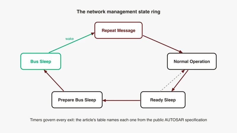
ECU testing over Ethernet means exercising the whole communication lifecycle, link-up, address assignment, time sync, service discovery, steady state, network release and bus sleep, not only steady-state message content, because most integration defects appear at the transitions. Network management is a first-class test target in that lifecycle: AUTOSAR specifies UDP-NM as three operational modes, Network Mode, Prepare Bus-Sleep Mode and Bus-Sleep Mode, with Network Mode holding the Repeat Message, Normal Operation and Ready Sleep states, and the transitions governed by configurable timers. A capture that starts after boot and stops before release cannot see any of it.
A ping proves that two IP stacks are alive at the same moment. It does not prove that the link trained at the right speed and role, that the switch put the port in the right VLAN, that the clock is disciplined, that any service was offered, or that anything will be released when the vehicle is parked. Yet “we pinged it” is still the first evidence produced when an integration problem is escalated.
The deeper problem is where the capture starts. A bench powers the device under test, waits for it to settle, then captures message content. That is the midphase, one of four; startup, shutdown and wake are the other three, and transitions are where integration defects live. Every network management state name, timer and semantic below was read out of the public AUTOSAR specifications named in the References.
What “ECU testing over Ethernet” covers, and what a ping does not prove
Four different pass conditions, routinely collapsed into one
Link, IP reachability, service reachability and application behaviour are separate conditions, and each can pass while the next fails.
Link means the physical layer trained at the right speed, role and pair, covered in our 100BASE-T1 bring-up checklist and T1 family guide. IP reachability means two endpoints can exchange datagrams, which is what a ping tests, and a link can be up while a VLAN misconfiguration leaves most peers unreachable. Service reachability means a provider offered something and a consumer resolved it, with its own state machine and failure modes; see our service discovery debugging article. Application behaviour means the ECU acts correctly on what it received and releases the network when done. Collapsing the four into “it responds” is how a defect reaches a vehicle.
Why a capture that starts after boot hides most integration defects
A capture opened after the ECU has settled cannot record what it did before it settled, and arming early needs a capture path independent of the device under test plus an operator willing to accept a file that mostly contains nothing.
Everything ordering-related is otherwise invisible. If an ECU transmits before its switch port is forwarding its VLAN, those frames are dropped and never appear anywhere; by the time the capture opens the ECU is transmitting successfully and looks correct. Arm the capture first, apply power second.
The communication lifecycle, and the three phases most benches skip
Startup
Startup runs from power applied to the first application message: rails and reset release, PHY configuration and link training, stack initialisation, address assignment, time sync convergence, network management entering Network Mode, service discovery, first payload. Each step depends on a predecessor and has a budget, and the interesting defects are ordering violations between adjacent steps. Where Ethernet sits in the wider architecture is covered in our vehicle communication architecture article.
Midphase
Midphase is steady state, where traffic is cyclic or event-driven and content is checkable against a database. Almost every lab measures it because it is stable and easy to automate, and it is where the fewest integration defects live, because every ordering question has already been answered.
Shutdown
Shutdown is the application releasing the network, network management coordinating a synchronised release, transmission stopping, and the physical layer going to sleep. The last two seconds before silence hold the evidence for the most common field complaint on an Ethernet vehicle network, that it never goes quiet.
Wake
Wake is a wake event travelling to the device under test across every intermediate device, each forwarding it because it was configured to. The whole startup sequence then repeats, so every startup defect is also a wake defect. Our TC10 sleep and wake article covers the physical layer half.
Startup defects: the first few hundred milliseconds
Ordering assumptions, and the ECU that transmits too early
An ECU whose stack comes up faster than the switch’s port configuration transmits into a port that is not yet forwarding its VLAN. The frames vanish and nothing logs an error, because the transmission succeeded and the switch is correctly dropping a frame on an unconfigured port. The observable is that first transmission relative to the port becoming operational, and it exists only in a capture armed before power.
Service discovery that runs before time sync is locked
Nothing in the service discovery state machine waits for a clock. The discovery phases worked through in our service discovery article, an Initial Wait Phase, a Repetition Phase and a Main Phase, run on their own delays with no dependency on gPTP, so discovery completes perfectly on an unsynchronised network. That is exactly why this defect survives to the vehicle.
The failure is one layer up: a consumer that resolves a service and immediately treats its payload timestamps as being on a synchronised base produces wrong results, silently, while the clock is still converging. On Linux the state to gate on is the servo reaching a locked state, which our gPTP troubleshooting article reads out of the daemon’s log line; where sync and scheduling fight, our Qbv and time sync article covers the interaction. So the test case is: record the servo state at the first payload whose consumer assumes a synchronised timestamp, and fail the run if it was not locked.
Conflicts that only appear on a cold power cycle, and behaviour after an update
A reset is not a cold start. It can leave an address lease, a cached neighbour entry, a bound socket or a switch forwarding entry alive somewhere, so a suite built entirely on resets never reproduces the conflict that appears the first time a vehicle is energised after sitting on a lot. Run the case from fully de-energised, on every device including the switch.
An ECU that has just been reprogrammed starts from a different initial condition again, with its own production-line constraints: see our article on Ethernet-based ECU programming.
UDP-NM: network management on an Ethernet vehicle network
What the state machine is for
AUTOSAR states the purpose plainly: the main purpose of the NM protocol is to coordinate one or more groups of ECUs to wake up and shutdown their communication stack synchronously. Power saving is a consequence. The objective is that everybody stops at the same time, so no ECU is still transmitting to peers that have gone.
The algorithm is decentralised and direct. Reception of an NM packet means the sender wants the cluster awake; a node that no longer needs communication stops sending but postpones its own sleep while it still receives NM packets, and when a timer elapses because none arrive, every node sleeps. That is the whole mechanism, and it diagnoses most shutdown defects.
The state set and the timers that govern it
AUTOSAR specifies three operational modes visible at the module interface, Network Mode, Prepare Bus-Sleep Mode and Bus-Sleep Mode, with Network Mode containing three internal states. Each row below carries the requirement it came from.
| State | Entered when | Timer governing the exit | What you should see on the wire |
|---|---|---|---|
| Bus-Sleep Mode | Set after initialisation; entered from Prepare Bus-Sleep Mode when the wait timer expires (SWS_UdpNm_00141, 00115) | None while resting. Left on a network request or passive start-up (SWS_UdpNm_00129, 00128) | No NM PDUs from this node. Receiving one notifies the upper layer rather than transitioning (SWS_UdpNm_00127) |
| Prepare Bus-Sleep Mode | NM-Timeout Timer expires in Ready Sleep State (SWS_UdpNm_00109) | UdpNmWaitBusSleepTime, then Bus-Sleep Mode is entered (SWS_UdpNm_00115) | Queues draining, then nothing. An NM PDU received here leaves the mode and re-enters Network Mode (SWS_UdpNm_00124) |
| Repeat Message State | Default state on entering Network Mode from either sleep mode (SWS_UdpNm_00095) | UdpNmRepeatMessageTime, then the state is left (SWS_UdpNm_00102) | Periodic NM PDUs restarted. On an active wakeup, where the network was requested and immediate transmissions are configured, the first PDUs use UdpNmImmediateNmCycleTime and no cycle offset (SWS_UdpNm_00334) |
| Normal Operation State | Repeat Message State left with the network requested, or Ready Sleep State on a new request (SWS_UdpNm_00103, 00110) | No exit timer. Left to Ready Sleep State on release (SWS_UdpNm_00118) | Periodic NM PDUs at UdpNmMsgCycleTime (SWS_UdpNm_00040) |
| Ready Sleep State | Repeat Message State left with the network released, or released in Normal Operation (SWS_UdpNm_00106, 00118) | NM-Timeout Timer, on whose expiry Prepare Bus-Sleep Mode is entered (SWS_UdpNm_00109) | Transmission stopped (SWS_UdpNm_00108), with narrow exceptions such as partial network shutdown messages |
Two consequences fall out of that table. The NM-Timeout Timer restarts on every NM PDU received and every one transmitted in Network Mode (SWS_UdpNm_00098, 00099), which is why one talkative node holds everybody. And the total from release to sleep is UdpNmTimeoutTime plus UdpNmWaitBusSleepTime (SWS_UdpNm_00088), which AUTOSAR notes should be configured identically in every node. Both of those hold where UdpNmStayInPbsEnabled is disabled; with it enabled the node stays in Prepare Bus-Sleep Mode until power off or a restart reason, which is itself worth confirming on the bench.
One decoding trap: the Foundation specification defaults the Control Bit Vector to Byte 0 and the Source Node Identifier to Byte 1, and the Adaptive Platform specification swaps them. Both are configurable defaults, so a decoder set up for one platform silently mis-reads the other.
Request and release semantics
Network states, requested and released, exist in parallel to the state machine, changed by an explicit request call and an explicit release call. That is the whole interface, and its simplicity is the problem: the pair has to balance.
The recurring defect is code that requests the network on some condition and releases it only on a path that is not always taken. Nothing errors. The node sits in Normal Operation State transmitting periodic NM PDUs exactly as specified, and because those restart the NM-Timeout Timer in every receiver, the whole cluster stays in Network Mode. AUTOSAR sets the state to released by default at initialisation, so an ECU that comes up already requesting took that request in its own startup code.
Remote Sleep Indication points straight at this: when enabled, it calls Nm_RemoteSleepIndication up to the generic network management interface when no NM PDUs have arrived for UdpNmRemoteSleepIndTime, meaning every other node is ready to sleep while this one keeps the bus awake.
Partial networking, and one node holding a cluster awake
Partial networking switches communication and function domains off across several ECUs while others keep communicating on the same channels. Every bit of the partial network information range represents one partial network, and a bit set to 1 requests it; a cluster is externally requested when a received message carries its bit set, internally requested when a local application requests it.
Two rules produce most of the surprises. A cluster not requested again within the reset time is considered not requested, so the request is a repeated assertion rather than a latch. And nodes must be pre-configured with the offset and range of that information within the NM message, so a mismatch between suppliers means one ECU reads another’s request bits at the wrong offset. One node with an unbalanced internal request keeps its whole cluster awake across the vehicle.
Shutdown defects: the ECU that will not let the bus sleep
Continuous transmission, and timeout parameters that disagree
The unbalanced request seen from the wire is a node transmitting periodic NM PDUs and carrying its own source node identifier while doing it. The network never goes quiet, and the diagnosis is not subtle once you have the capture.
The subtler case is configuration. AUTOSAR notes that UdpNmTimeoutTime and UdpNmWaitBusSleepTime should have the same values in all nodes, and that the transition into Bus-Sleep Mode then happens at approximately the same time everywhere. When two suppliers configure different values the cluster still sleeps, just not together: the node with the shorter timeout enters Prepare Bus-Sleep Mode first, and if anyone is still transmitting when it does, receiving an NM PDU in that mode leaves it and re-enters Network Mode. On a capture that reads as a network that almost goes quiet, over and over.
Some residual spread is expected even when configuration matches, and the specification names its sources: clock precision and oscillator drift, the NM task cycle time, and PDUs waiting in the transmit queue. A large or growing spread is a mismatch.
Sleep coordination against the physical layer
The division of labour matters: network management decides whether the cluster should sleep, and the physical layer sleep and wake mechanism executes the link shutdown. The OPEN Alliance specification puts which nodes get switched off explicitly outside its own scope and leaves it to network management; our TC10 article works through the handshake and its bounded timers.
The failure at the seam is a link whose sleep handshake fails after network management has already released. The PHY does expose the failure, via the sleep-abort primitive and, on most silicon, an interrupt flag, but nothing in the NM state machine consumes it. A test that only decodes NM traffic records a clean release and misses a link that stayed up, so read the PHY flag as a separate observable.
Diagnosing it: capture the last two seconds and work backwards
Leave the capture running well past the instant you expected sleep, find the last NM PDU, and read its source node identifier with the position confirmed against the platform configuration. Then work backwards: was that node in Normal Operation State transmitting cyclically, or was it one late frame that restarted everybody’s timeout? Repeat several times. A consistent offender is a request that is never released; a rotating offender is usually a timeout mismatch.
Test cases you can write this week
The capture methods below are categories, not products; choosing between them is covered in our capture methods guide.
| Phase | Stimulus | Observable | Pass criterion | Capture method |
|---|---|---|---|---|
| Startup | Cold power-on, fully de-energised | First frame sent | Nothing before the link is up and the port forwards its VLAN; first frame is the type the role specifies | Inline tap, armed before power |
| Startup | Cold power-on | Link up to first NM PDU | Within budget on every run of N, not on the median | Inline tap, disciplined clock |
| Startup | Cold power-on | Servo state at the first application payload | Locked before any payload assuming a synchronised timestamp | Tap plus sync daemon log |
| Startup | Cold power-on | Repeat Message State entry and duration | Entered by default on Network Mode entry, left only after UdpNmRepeatMessageTime | NM decode on the tap |
| Startup | Cold power-on, one peer held down | Behaviour with a missing peer | Degrades as specified; does not release the network for others | Tap plus peer simulator |
| Midphase | Steady state, 60 s window | NM interval and jitter | Matches UdpNmMsgCycleTime; no gap long enough to expire a peer’s timeout | Tap, per-frame delta analysis |
| Midphase | Delay one provider’s startup | Consumer behaviour in the gap | Specified degraded behaviour, no unhandled state | Tap plus peer simulator |
| Shutdown | Apply the application release condition | NM PDU transmission | Stops, apart from the specified Ready Sleep State exceptions | Tap |
| Shutdown | Release every node | Last NM PDU to the bus sleep instant | Matches UdpNmTimeoutTime plus UdpNmWaitBusSleepTime | Scope on the pair or current probe, or the Nm_BusSleepMode callback logged on the DUT, with a tap for the last NM PDU timestamp |
| Shutdown | Release every node, N times | Source node identifier of the last NM PDU | The expected node every run; the device under test appearing consistently is its own defect | NM decode, identifier position confirmed |
| Shutdown | Release every node | Link state and current after the NM sleep instant | Link sleeps after the release; quiescent current reaches target | Scope on the pair plus current probe |
| Wake | Wake injected at the far end of the wake path | Wake arrival | Link comes up and the startup rows above pass again | Tap and scope at each hop |
| Wake | Network request during Prepare Bus-Sleep Mode | Return to Network Mode | Mode left and Network Mode entered on the request or a received NM PDU | Tap |
| Brown-out | Dip below the reset threshold, restored after a set interval | Restart behaviour | Clean restart into Repeat Message State, no stale NM state | Programmable supply, tap, current probe |
Repeatability, brown-out and negative cases
Run the same cold start thirty times and record the interval to each milestone rather than a pass or fail. A tight cluster with one outlier is a race condition that loses occasionally, and it will lose in the field too; a spread wide on every run means a milestone is gated on something asynchronous nobody intended.
A supply that dips below the reset threshold and recovers quickly is a different stimulus from a clean power cycle, because parts of the ECU may not have fully de-energised. Sweep the dip depth and duration rather than testing one point.
The criteria above are mostly about good behaviour. The cases that find real defects are the ones where a peer misbehaves: hold one down, delay one past the consumer’s timeout, stop one mid-session, and check that the device under test degrades as its specification says. If the specification does not say, that is the finding, and it is worth more than the test.
Instrumenting the test correctly
Where to tap
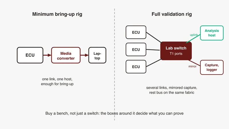
A tap on the device under test’s own link shows what it sent and what reached it, which covers most rows above. Where a criterion is about the cluster, such as which node sent the last NM PDU, you need every transmitter, which usually means capturing at the switch. Trade-offs between an inline tap, a mirror port and a media converter are in our capture methods guide, and the media choice in our media converter guide.
Which clock stamped the capture
Every timing number here is a difference between two timestamps, and events stamped by different instruments on undisciplined clocks carry their offset, their relative drift and both jitters. Proving the time base itself is the subject of validating time sync.
Correlating with CAN and the power rails
A wake often originates on another bus or a hard wire, a release decision may be triggered by a CAN signal, and the shutdown criterion that matters is a current measurement. One timeline for that is in our multi-bus correlation article, the encapsulation formats carrying a per-event timestamp in our capture encapsulation article. Where diagnostics are in scope, see diagnostics over IP and P2 timeouts.
How this fits with rest bus simulation and HIL
Almost every criterion above needs peers you can control: hold one down, delay one, stop one mid-session, make one transmit late. That is the rest bus job, and it is what lifecycle testing depends on most while midphase testing barely uses it. A bench built for steady state has peers that either exist or do not; a bench built for lifecycle testing has peers with a start time, a stop time and a fault injection point.
Where the plant matters is narrower than usually assumed. If the application’s own request and release decisions depend on simulated vehicle state, a HIL model earns its place in the communication suite; if they do not, it adds cost without lifecycle coverage, and the money is better spent on controllable power and a self-arming capture. Promotion into regression then follows what automates: cold start repeatability, the release-to-sleep interval and the negative cases all reduce to a timestamp difference, while cases needing a scope on the pair and a current probe usually stay manual.
Where GSAS fits
Most of the value here is in deciding what your bench can and cannot observe before anything is specified. We work through the four phases with your team: which your current setup captures at all, where the capture is armed relative to power, which pass criteria are written down and which are assumed, and which timing numbers depend on a clock nobody has characterised.
The second conversation is a review of your test plan against the lifecycle checklist above, phase by phase, with attention to the two areas usually thin. Shutdown cases are cheap to add and catch the defect behind the most field escalations. Negative cases are where a missing pass criterion is itself the finding.
GSAS is an engineering partner, so our applications engineers work alongside teams in Bengaluru, Pune, Chennai and Hyderabad on bench layout and test plan review rather than delivering a report from a distance. Our automotive Ethernet capability page sets out how we work with engineering teams, and you can request a consultation describing your setup and the phases you currently cover.
References
- AUTOSAR, Specification of the AUTOSAR Network Management Protocol, Foundation Release 1.5.1, document 928 (purpose, coordination algorithm, Control Bit Vector defaults, partial networking PRS_Nm_00335 to 00341, PnResetTime semantics PRS_Nm_00340, timeout parameters): https://www.autosar.org/fileadmin/standards/R19-03/FO/AUTOSAR_PRS_NetworkManagementProtocol.pdf
- AUTOSAR, Specification of UDP Network Management, Classic Platform R21-11, document 414 (modes and states SWS_UdpNm_00092 to 00129, network states 00104 and 00105, initialisation 00141 and 00143, Remote Sleep Indication 00149 to 00151, partial network reset parameter UdpNmPnResetTime): https://www.autosar.org/fileadmin/standards/R21-11/CP/AUTOSAR_SWS_UDPNetworkManagement.pdf
- AUTOSAR, UDP Network Management Protocol Specification, Adaptive Platform Release 17-10, document 856 (modes PRS_UdpNm_00092 to 00129, message format and default byte positions PRS_UdpNm_00074 and 00075): https://www.autosar.org/fileadmin/standards/R17-10_R1.2.0/AP/AUTOSAR_PRS_UDPNetworkManagementProtocol.pdf
- AUTOSAR standards index, Classic Platform: https://www.autosar.org/standards/classic-platform
- OPEN Alliance specification register, for the sleep and wake-up specifications referenced above: https://opensig.org/
Also appears in:
Building for Automotive & Mobility?
Talk to our application engineers for personalized tool recommendations.