In short
A 100BASE-T1 media converter is a two-port PHY bridge that translates a single-twisted-pair automotive Ethernet link into standard RJ45 Ethernet, so a laptop or lab switch can join an in-vehicle network. It is not a fibre media converter, not a switch and not a protocol gateway. Because it contains a T1 PHY it holds a master or slave role of its own, which has to be the complement of the role on the ECU port it faces.
The converter is the first thing an automotive Ethernet programme buys and the last thing anyone specifies. It gets ordered because a laptop cannot plug into a T1 pair, it arrives, the link does not come up, and days later somebody discovers the box holds a master or slave role that nobody thought about.
The pages that sell these boxes document their own DIP switches and assume you already chose. This is the part before that: what the box does at the physical layer, when it is the wrong box, and the nine criteria that decide whether a unit fits your bench. Every standards claim traces to a source in the References.
One qualification first, because the search results fight you on it. A copper-to-fibre media converter, the kind that bridges RJ45 Ethernet to an optical port for reach across a building, has nothing to do with this. If a listing does not say 100BASE-T1, 1000BASE-T1, IEEE 802.3bw, IEEE 802.3bp or BroadR-Reach, and does not discuss master and slave roles, it is not this product.
What a 100BASE-T1 media converter actually does
One twisted pair, full duplex, versus the four-pair PHY on your laptop
The IEEE P802.3bw objectives set the shape of the problem: 100 Mbit/s in automotive environments, for example EMC and temperature, over a single balanced twisted pair, full duplex only, over a link segment with up to four inline connectors using balanced cabling for at least 15 m of reach. The task force completed with the approval of IEEE Std 802.3bw-2015 on 27 October 2015.
Both directions occupy that one pair at once, each receiver subtracting its own transmission to recover the far end’s. The office physical layer on your laptop splits the job across four pairs and terminates in RJ45. The two meet at neither the connector, the pair count nor the line code, which is why a passive adapter cable cannot exist.
Why it is a PHY-to-PHY bridge and not a protocol gateway
The converter terminates the T1 link, recovers the frames and re-originates them on a standard Ethernet PHY. Nothing above the MAC is inspected or rewritten, so the SOME/IP, DoIP or UDS traffic on the RJ45 side is what was on the pair.
Two consequences: it is a participant on the link rather than an observer, so inserting it takes the link down, and it holds one of the link’s two roles.
The naming you will meet: 802.3bw, 802.3bp and BroadR-Reach
100BASE-T1 is IEEE Std 802.3bw-2015. 1000BASE-T1 is IEEE Std 802.3bp-2016, approved 30 June 2016, a different physical layer rather than a faster mode of the same one. BroadR-Reach is the pre-standard ancestor: the 802.3bw objectives carry an objective to provide electrical interoperability with the existing single balanced twisted pair 100 Mbit/s client interface, footnoted to the BroadR-Reach specification hosted on the IEEE 802.3 site. A listing that says BroadR-Reach means the ancestor of 100BASE-T1, not automotive Ethernet as a whole.
The T1 family explained has the variant table, and what automotive Ethernet is is the wider primer.
Converter, switch, or tap: pick the right box first
One link, transparent, no forwarding decisions: converter
One T1 link, a host on the end of it. No forwarding decisions, no address table, one device in the path.
Several links and forwarding decisions: lab switch
Three ECUs and a host on one network needs something that forwards between ports: a lab switch with T1 ports. Two converters into a desktop switch is the usual improvisation, and it holds until you need VLANs, mirroring or per-port speed control.
Observe without joining the network: tap or mirror
If the traffic you want is between two other devices and you must not become one of them, you want a tap or a switch mirror port. Our capture guide owns that choice.
The failure mode of each wrong choice
| You bought | The failure mode when it is the wrong box |
|---|---|
| Media converter | You needed to watch two other devices talk, and your host is now one of them |
| Lab switch with T1 ports | Overkill for one link, and its port roles are a second thing to debug |
| Tap | You cannot send anything, so it is useless for diagnostics or flashing |
| Mirror port already in the path | Frames dropped silently under load, timing altered, tags maybe stripped |
Master and slave: the setting that decides whether the link comes up
Why 100BASE-T1 fixes the role instead of negotiating it
Because the link has one clock and someone has to own it. During IEEE P802.3bw D1.2 working group ballot a commenter asked to add negotiable MASTER and SLAVE functionality, and the task force rejected it, recording that this type of network does not have plug and play functionality, it is a pre-configured embedded network. The draft clause text states that the 100BASE-T1 PHY MASTER-SLAVE relationship is set by FORCE mode.
The ethtool manual describes what the roles do: as MASTER the PMA transmit function sources TX_TCLK from a locally generated clock, as SLAVE from the clock recovered from the MASTER’s data stream. Two masters means two free-running clocks and nothing to recover.
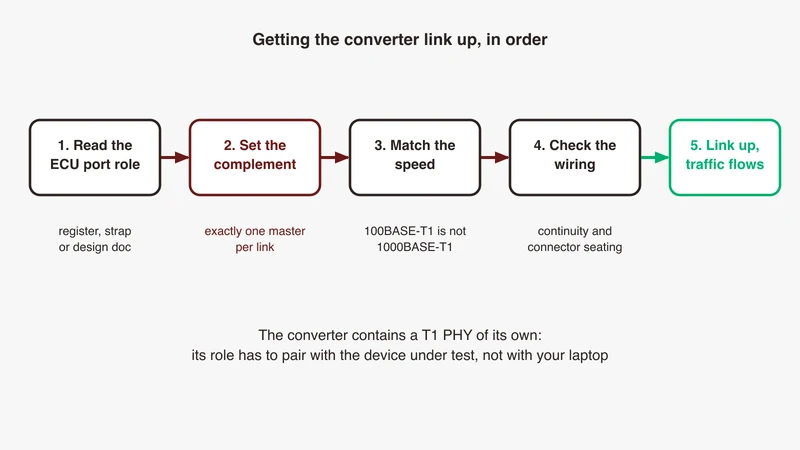
Reading the role on the ECU side and setting the converter to the complement
Read first, then set. On a Linux host that owns the PHY, ethtool exposes forced-master and forced-slave, which the manual notes can be used without auto-negotiation, and the netlink interface carries a master/slave port mode and a separate master/slave port state, so you can compare what you asked for against what the port reports. Behind a managed switch the setting lives in the switch’s own configuration, and the manual’s caveat applies throughout: not all devices support this.
Then set the converter to the opposite. If you cannot read the ECU side, try one setting then the other and record which worked, because that is a fact about your link that belongs in the interface control document.
The classic false positive: blaming P and N polarity
When a link will not come up, re-pinning P and N is the first thing most people try, and where the PHY implements the optional automatic polarity detection of 802.3bw, it does not matter. The 802.3bw ballot text describes polarity detection and correction at the earliest link-up stages: if a polarity flip is detected, the SLAVE changes the sign of its received signals to correct the polarity, and also of its transmitted signals, so polarity is always observed as correct by the MASTER PHY.
A swapped pair on its own is therefore usually not the reason for no link, provided both PHYs implement that optional correction. Continuity, shorts, breaks and a role clash are. The ordered version of that hunt is our bring-up checklist.
Speed mismatch: 100BASE-T1 hardware facing a 1000BASE-T1 port
A correct role is not sufficient. The two are different clauses of different amendments, with different symbol rates and line codes, and nothing on the pair adapts one to the other. A converter forced to 100BASE-T1 facing a port forced to 1000BASE-T1 will not link at any role setting, and the symptom looks exactly like a role clash.
When this is not a converter problem at all
The converter is one of about ten candidates for a link that will not come up, and not the first. Power and reset, continuity, the connector count against the link segment, the PHY answering on its management bus, and the roles at both ends come first. Work the checklist in order rather than swapping the converter, the expensive way to test the cheapest hypothesis.
The criteria that actually decide fitness
Nine criteria decide whether a unit fits your bench. The cells below are questions rather than answers, deliberately: each answer is a property of a specific product, and we will not invent a specification for a category.
| Criterion | The question to ask the supplier | Why it decides fitness |
|---|---|---|
| Role configuration | Settable per T1 port, set how, and does it survive a power cycle? | The role is not negotiated. One fixed to a single role suits only ECUs holding the other |
| PHY and speed mix | 100BASE-T1 only, or 100 and 1000BASE-T1, switchable per port or per unit? | Different amendments, no adaptation on the pair |
| Latency and buffering | What is the latency, is it fixed or load dependent, is the path store-and-forward? | A constant offset can be subtracted from a measurement, a variable one cannot |
| Link-state mirroring | If the T1 side drops, does the RJ45 side drop too, and how fast? | Without it your host sees a live interface on a dead link, and a failed ECU looks silent |
| Timing asymmetry | Are the ingress and egress latencies equal, and characterised? | gPTP peer delay assumes the directions match. Asymmetry biases every offset |
| TC10 passthrough | Does the T1 side respond to LPS, can sleep be inhibited, is wake state exposed? | The specification’s wakeup forwarding is written around devices with more than one T1 PHY |
| Connector family | Which family on the T1 side, fixed socket or re-terminable flying lead? | Whatever your harness terminates. Each mated pair counts against the connector budget |
| Power and isolation | Bus or externally powered, is the T1 side isolated, what supply range? | Cranking and brown-outs on a vehicle supply. Ground loops are a real fault source |
| Configuration surface | DIP switches, USB utility or web interface, and can state be read back? | A switch is visible and unscriptable, a software setting scriptable and invisible |
Latency and buffering: the number matters less than its variance
The whitepaper cited in the References puts the rule plainly: any active device that touches a frame has changed the frame timing, and it is essential to keep all changes by a device linear, because if the frame offset was 10 ms then all frames should have the same offset, and if not, the device is interfering with real-time analysis at that access point. Characterise a fixed offset once and subtract it. An offset that moves with load you cannot repair.
Timing asymmetry: what biases gPTP
gPTP corrects path delay one link at a time with the peer delay mechanism, which assumes both directions are equal. A transparent converter is not a time-aware bridge, so nothing in the domain measures or removes the time a frame spends inside it. linuxptp gives you the correction and the failure mode: delayAsymmetry is documented as the time difference in nanoseconds of the transmit and receive paths, ingressLatency and egressLatency correct characterised hardware delay at each end, and neighborPropDelayThresh is an upper limit above which the port is marked as not 802.1AS capable. Our gPTP troubleshooting guide shows that in the logs.
TC10 passthrough: read the requirement before you ask for the feature
The public OPEN Alliance Sleep/Wake-up Specification version 2.0 defines LPS as a sleep request to the link partner, WUR as a wake-up request sent over an active link during IDLE times, and WUP as a pulse used when the link is down. It requires multi-PHY devices such as switches to implement a selective wakeup forwarding mechanism, forwarding a request detected on one port to the device’s other PHYs.
A converter has one T1 PHY and one standard Ethernet PHY, and nothing on the RJ45 side to forward a WUP onto, though the specification also defines forwarding over a wakeup pin, so ask whether the unit exposes one. So the realistic questions are about the T1 side: does it honour a sleep request and drop your bench link mid-session, can that be inhibited, and can it wake a sleeping ECU. The TC10 article covers the protocol.
Connectors, power and the configuration surface
IEEE 802.3bw defines its link segment as up to 15 m of a single balanced twisted-pair cable with up to four inline connectors and two end connectors, and names no connector family. H-MTD, MATEnet and MQS are supplier product families you meet on harness drawings, so the compatible answer comes from the drawing, not the standard. Count the mated pairs the converter adds against that budget of four.
On power, ask the supply range and whether the T1 side is isolated from the host, because a bench that works on a desk can find a ground loop once a vehicle is involved. Whichever configuration surface it has, insist on reading the state back.
Where a converter distorts your measurement, and where it does not
A transparent bridge is not a PTP-aware bridge
The distinction is between a device that participates in the timing domain and one that merely passes frames. A converter is the second kind: its delay is real, measured only as part of the link’s peer delay rather than removed as a time-aware bridge would remove it, and added in both directions. Irrelevant for protocol content, a systematic error inside your instrument for delay, jitter or scheduling work.
Why the converter is a poor timestamp reference
A timestamp taken through a converter is applied by your host, after the frame has crossed the converter, the cable and the host’s network stack: an uncharacterised offset on top of scheduler jitter. That is not a reason to avoid converters, it is a reason not to quote a number from that path without saying where the timestamp came from.
When you move up to hardware timestamping
When the answer you need is a number rather than a sequence, the converter and host NIC combination runs out and a capture module with its own hardware timestamping earns its cost. The trade-offs are in our capture guide.
Bench setups that work
Laptop to a single ECU, the minimum rig
Host, RJ45 patch lead, converter, T1 lead to the ECU. Set the converter to the complement of the ECU role, confirm both ends are on the same speed, and confirm the link before blaming anything above it. If frames arrive but will not decode, the SOME/IP decoding fix list is next.
Converter plus lab switch for multi-node bring-up
Two or three converters into a desktop switch gets several ECUs and a host onto one broadcast domain. A legitimate stopgap, until you need VLAN separation, per-port mirroring or traffic shaping.
Converter in a mirror path feeding a packet capture
If the T1 link already lands on a lab switch, mirror that port and run the converter from the mirror output rather than breaking the link. You inherit every mirror limitation our capture guide sets out. Where the question is the waveform rather than the frames, a scope is the instrument, covered in our bus decode guide.
What a converter cannot do: production-line ECU work
A converter is bench equipment. End-of-line programming over automotive Ethernet is a different discipline, with its own cycle time, determinism and station integration requirements, covered in our walkthrough of flashing over automotive Ethernet.
Buying one in India: qualifying the shortlist
The fibre problem, restated
Indian search results for “ethernet media converter” return mostly copper-to-fibre products, whose listings are keyword-rich enough to survive a query that includes “automotive”. Filter on the words only the right product uses: 100BASE-T1, 1000BASE-T1, IEEE 802.3bw, IEEE 802.3bp, BroadR-Reach, and master or slave role selection. A datasheet that never mentions a role is not a T1 device.
Import, lead time and invoicing
Settle the import questions before the purchase order: who holds the stock, who is the importer of record, what the invoicing entity and currency are, and what happens to a unit that has to go back. None of it is technical, and all of it decides when the converter reaches the bench.
Six questions to ask a supplier before the purchase order
- Is the master and slave role settable per T1 port, and does the setting survive a power cycle?
- Does the RJ45 side drop when the T1 side drops, and how quickly?
- What is the device latency, is it fixed or load dependent, and are the two directions equal?
- What does the T1 side do when it receives a sleep request, and can that be inhibited?
- Which connector family is on the T1 side, and can it be re-terminated to ours?
- Who supports it in India, in IST, and what is the process for a return or a replacement?
Get the answers in writing. Each is a property the supplier knows and the datasheet omits, and one who cannot answer the first four is selling a box, not an instrument.
Where GSAS fits
GSAS Micro Systems is an engineering partner, and on a converter the useful first conversation is about the bench, not the box. Which link are you bringing up, who owns the role assignment on the ECU side, will anything in your analysis be quoted as a number, and does the link need to sleep. Those four answers cut most of a shortlist.
Our applications engineers work in IST, so a bench session lands inside your working day, and the teams we work with sit in Bengaluru, Pune, Chennai and Hyderabad. We will go through your topology, score a shortlist against the nine criteria above, and tell you which questions your supplier has not answered.
Start with the automotive Ethernet capability page, then request a scoped conversation with your link description and bench goal. Where the answer is that your existing hardware already does this, that is the answer you get.
References
- IEEE P802.3bw 100BASE-T1 Task Force (IEEE Std 802.3bw-2015 approved 27 October 2015): https://www.ieee802.org/3/bw/
- IEEE P802.3bw adopted objectives, v0.6, 17 July 2014 (100 Mbit/s in automotive environments over a single balanced twisted pair; full duplex only; electrical interoperability with the existing single balanced twisted pair 100 Mbit/s client interface, footnoted to the BroadR-Reach specification on the IEEE 802.3 site; link segment with up to four inline connectors, balanced cabling, at least 15 m reach): https://www.ieee802.org/3/bw/public/20140717_V3_Objectives.pdf
- IEEE P802.3bw D1.2 approved working group ballot comments (MASTER-SLAVE relationship set by FORCE mode; rejection of negotiable MASTER and SLAVE functionality, recorded as a pre-configured embedded network; the SLAVE correcting a polarity flip by changing the sign of its received and transmitted signals; link segment of up to 15 m with up to four inline and two end connectors): https://www.ieee802.org/3/bw/comments/8023bw_D1_2_approved.pdf
- IEEE P802.3bp 1000BASE-T1 PHY Task Force (IEEE Std 802.3bp-2016 approved 30 June 2016): https://www.ieee802.org/3/bp/
- OPEN Alliance specification index: https://opensig.org/automotive-ethernet-specifications/
- OPEN Alliance, “OPEN Sleep/Wake-up Specification”, v2.0, final, public, 21 February 2017 (LPS; WUR sent over an active link during IDLE times; WUP sent when the link is down; multi-PHY devices such as switches shall implement selective wakeup forwarding): https://opensig.org/wp-content/uploads/2024/01/TC10-Wake-up-and-Sleep-Specification-for-Automotive-Ethernet_11-2017.pdf
- Linux ethtool manual page (forced-master and forced-slave, usable without autonegotiation; TX_TCLK sourcing per role; “Not all devices support this”): https://man7.org/linux/man-pages/man8/ethtool.8.html
- Linux kernel ethtool netlink documentation (master/slave port mode and master/slave port state): https://docs.kernel.org/networking/ethtool-netlink.html
- linuxptp ptp4l manual page (delayAsymmetry, ingressLatency, egressLatency, neighborPropDelayThresh): https://manpages.debian.org/unstable/linuxptp/ptp4l.8.en.html
- Network-visibility vendor whitepaper, “TAP vs SPAN: Best Practice Guide to Improving Network Visibility” (any active device that touches a frame has changed the frame timing; keep all changes by a device linear): https://www.garlandtechnology.com/hubfs/Current/Documents/Whitepaper/GTWP-TAP-vs-SPAN21.pdf
Also appears in:
Building for Automotive & Mobility?
Talk to our application engineers for personalized tool recommendations.