In short
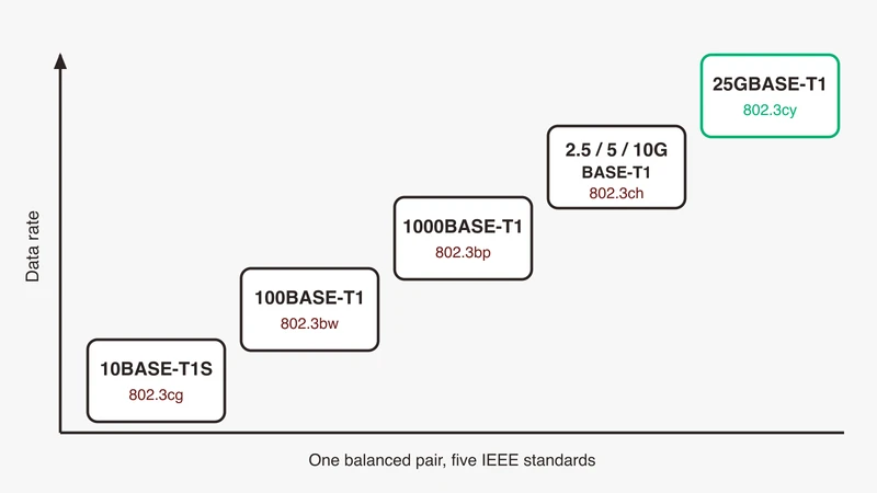
The T1 family is the set of single-pair Ethernet physical layers in IEEE 802.3: 10BASE-T1S and its industrial sibling 10BASE-T1L (802.3cg), 100BASE-T1 (802.3bw), 1000BASE-T1 (802.3bp), 2.5/5/10GBASE-T1 (802.3ch) and 25GBASE-T1 (802.3cy). The automotive members are 10BASE-T1S and above; 10BASE-T1L targets process and building automation. All carry the unchanged Ethernet frame over one balanced pair, and reach shortens as the rate climbs.
Every T1 variant is documented, but one at a time, inside a datasheet for one part number, with the reach quoted as a bare number and no conditions attached.
This article is the map: one table covering every T1 physical layer in IEEE 802.3, with rate, symbol rate, line code, specified reach and cabling. Then the two questions that keep coming back: why 100BASE-T1 has no auto-negotiation, and why one end must be master.
Every figure below traces to a public IEEE 802.3 task force document, an IEEE SA hosted presentation, a public OPEN Alliance page or the Linux ethtool and kernel documentation, named in the References. Nothing comes from a paywalled clause.
What “T1” means in an Ethernet name
Reading 100BASE-T1: rate, baseband signalling, single balanced pair
IEEE names its physical layers in three parts. The leading token is the rate, in Mbit/s on the older names (10, 100, 1000) and in Gbit/s once a G is appended (2.5G, 5G, 10G, 25G). BASE means baseband signalling: the signal occupies the cable directly rather than modulating a carrier. The suffix describes the medium, and T means twisted pair.
The trailing 1 is the automotive story. One balanced twisted pair, not the four pairs office gigabit Ethernet uses. Everything else follows from that.
T versus TX, T1, T1S and T1L
Four suffixes turn up in the same conversations and mean different things.
T and TX are the office physical layers on structured four-pair cabling, terminated in RJ45.
T1 is a single balanced pair. From 100 Mbit/s upward the T1 PHYs are point to point and full duplex only, using echo cancellation so both directions occupy the same pair simultaneously; 10BASE-T1S is the exception, half duplex by default with full duplex and multidrop both optional.
T1S, short, is the short-reach 10 Mbit/s member, Clause 147 of IEEE 802.3cg. It is the only member of the family where more than two nodes can share a pair.
T1L, long, is the long-reach 10 Mbit/s member, Clause 146 of the same amendment, aimed at process and building automation rather than vehicles. It is why a search for 10BASE-T1S returns industrial results next to automotive ones: both PHYs came out of IEEE Std 802.3cg-2019, which the task force site records as approved on 7 November 2019.
Why automotive picked one pair
The 802.3bw objectives say it plainly: support 100 Mbit/s operation in automotive environments, for example EMC and temperature, over a single balanced twisted pair, while preserving the IEEE 802.3 frame format and the minimum and maximum frame size of the current standard. One pair means fewer conductors in the harness; the preserved frame means the stack above the MAC is untouched.
The full T1 comparison table
Every T1 variant in one place
| Variant | Standard, clause | Rate | Symbol rate, line code | Reach as specified | Duplex, topology | Cabling |
|---|---|---|---|---|---|---|
| 10BASE-T1S | 802.3cg-2019, Cl 147 | 10 Mbit/s | 12.5 MBd, 4B/5B differential Manchester, no FEC | Link segment at least 15 m; mixing segment at least 25 m, at least 8 nodes | Half duplex point to point; optional full duplex; optional half duplex multidrop | Unshielded balanced pair |
| 10BASE-T1L | 802.3cg-2019, Cl 146 | 10 Mbit/s | 7.5 MBd, PAM-3, 4B3T, no FEC | At least 1 km, up to 10 inline connectors (1000 m on 18 AWG) | Full duplex, point to point | Balanced pair |
| 100BASE-T1 | 802.3bw-2015, Cl 96 | 100 Mbit/s | 66.666 MBd, PAM-3 ternary symbols via 4B3B | Up to 15 m, up to 4 inline plus 2 end connectors | Full duplex only, point to point | Unshielded balanced twisted pair |
| 1000BASE-T1 | 802.3bp-2016, Cl 97 | 1 Gbit/s | 750 MBd, PAM-3, 81B coding, RS-FEC | Type A at least 15 m; Type B at least 40 m; both up to 4 inline connectors | Full duplex only, point to point | Type A unshielded balanced copper; Type B balanced copper |
| 2.5GBASE-T1 | 802.3ch-2020, Cl 149 | 2.5 Gbit/s | 1406.25 MBd, PAM-4 (PAM-2 training) | At least 15 m, up to 4 inline connectors | Full duplex only, point to point | Single shielded balanced pair |
| 5GBASE-T1 | 802.3ch-2020, Cl 149 | 5 Gbit/s | 2812.5 MBd, PAM-4 (PAM-2 training) | At least 15 m, up to 4 inline connectors | Full duplex only, point to point | Single shielded balanced pair |
| 10GBASE-T1 | 802.3ch-2020, Cl 149 | 10 Gbit/s | 5625 MBd, PAM-4 (PAM-2 training) | At least 15 m, up to 4 inline connectors | Full duplex only, point to point | Single shielded balanced pair |
| 25GBASE-T1 | 802.3cy-2023, Cl 165 | 25 Gbit/s | 14.0625 GBd, PAM-4 (PAM-2 training) | At least 11 m, up to 2 inline connectors | Full duplex only, point to point | Single shielded balanced pair |
Bit error ratio objectives differ too: 10 to the minus 10 for 802.3bw, 802.3bp and 802.3cg on segments up to 25 m, and 10 to the minus 12 for 802.3ch and 802.3cy.
How to read the reach column
None of those metre figures is a promise about your harness. Two kinds of statement sit in that column.
A task force objective is a design target agreed before the standard was written. The 802.3ch objectives ask for at least 15 m over an automotive link segment supporting up to four inline connectors, on at least one type of automotive cabling, with candidate types listed as UTP, STQ, STP, SPP, coax or twinax. That is a floor with conditions, not a maximum.
A link segment definition is the channel the electrical specification was written against. For 100BASE-T1 the ballot resolution defines it as up to 15 m of single balanced twisted-pair cable, up to four inline connectors and two end connectors. Change the connector count or the cable and you are outside that channel, whether or not the length still reads 15 m.
So when a datasheet quotes a bare number, ask what connector count and cable type it assumes.
100BASE-T1 (IEEE 802.3bw)
From BroadR-Reach to an IEEE standard
100BASE-T1 did not start at IEEE. Before it there was BroadR-Reach, a single-pair automotive physical layer published through the OPEN Alliance, whose specification is hosted publicly on the IEEE 802.3 site. The P802.3bw objectives carry an explicit objective to provide electrical interoperability with that existing single balanced twisted pair 100 Mbit/s client interface, footnoted to that document.
That is the whole relationship. BroadR-Reach is the ancestor of one member of the T1 family, not a synonym for automotive Ethernet, and treating it as one causes confusion in supplier conversations where both terms appear in the same requirement.
Reach and cabling assumptions
The 802.3bw objectives ask for a link segment and PHY supporting point-to-point operation over a single twisted pair with up to four inline connectors using balanced cabling for at least 15 m of reach, full duplex only, at a bit error ratio of 10 to the minus 10 or better. The ballot resolution that became the clause text fixes the channel: up to 15 m of a single balanced twisted-pair cable, up to four inline connectors and two end connectors, carrying 100 Mbit/s in each direction simultaneously, on unshielded twisted pair.
No auto-negotiation: what that means for bring-up
The same objectives sheet asks for fast startup using predetermined configurations, from power on to a state capable of transmitting and receiving valid data in under 100 ms. The drafters originally wrote that reason into the text: the PHY does not use auto-negotiation because of latency that does not meet automotive start-up requirements. That sentence was struck during ballot as contrary to the objective that the standard would not preclude single-pair auto-negotiation, leaving only the operative statement that the relationship is set by FORCE mode. Clause 98 auto-negotiation, when it did arrive in 802.3bp, completes in under a millisecond, so the real reason is the one the task force gave when it rejected negotiable roles: this is a pre-configured embedded network.
When a commenter asked for negotiable MASTER and SLAVE functionality, pointing out that two PHYs both provisioned as MASTER, or both as SLAVE, will not operate correctly, the task force rejected it, recording that this type of network does not have plug and play functionality.
So a dead 100BASE-T1 link is a configuration question before it is a hardware question. Check the roles first.
1000BASE-T1 (IEEE 802.3bp)
Link segment types, and the shielded versus unshielded question
The Clause 97 draft defines two link segments, and the difference between them is reach and application, not shielding:
- Type A, an automotive link segment supporting up to four inline connectors using unshielded balanced copper cabling for at least 15 metres.
- Type B, an additional link segment supporting up to four inline connectors using balanced copper cabling for at least 40 metres, to support applications requiring additional physical reach such as industrial and automation controls and transportation, including aircraft, railway, bus and heavy trucks.
Worth stating, because Type A and Type B are often described as the unshielded and shielded options and the standard does not say that. Type A is the one explicitly specified on unshielded cabling. The OPEN Alliance publishes 1000BASE-T1 channel and component requirements in both STP and UTP variants, which is where the shielding choice actually gets made.
Electrically, 1000BASE-T1 is PAM-3 at 750 MBd with a 15-bit scrambler for EMC, 81B block coding, and a 396-bit Reed Solomon FEC code on each group of forty-five 81B blocks to hold the bit error ratio at 10 to the minus 10 or better.
Where gigabit gets used in a vehicle
The rate follows the load. Gigabit links carry sensor aggregation and backbone traffic between compute nodes, where 100 Mbit/s runs out and the multi-gig cabling and EMC cost is not yet justified. For where each class sits in a vehicle, see Ethernet in the vehicle communication architecture; for the stack above the pair, the complete automotive Ethernet guide.
Interop with 100BASE-T1 happens in a switch, not in a cable
No cable makes a 100BASE-T1 port talk to a 1000BASE-T1 port. Different clauses, different symbol rates, different coding.
Clause 98 auto-negotiation, introduced by 802.3bp for single differential-pair media, does exchange abilities between two devices sharing a link segment: its base page carries 100BASE-T1 ability, 1000BASE-T1 ability, MASTER and SLAVE configuration and flow control ability, and it completes in under a millisecond. But it is optional, both ends have to implement it, and it resolves to a common ability rather than translating between two fixed ones. A port forced to 100BASE-T1 and one forced to 1000BASE-T1 will not link.
What bridges the two rates is a switch with one port of each type. The frames cross unchanged, because every T1 project preserves the Ethernet frame format at the MAC client service interface.
10BASE-T1S and PLCA (IEEE 802.3cg)
Multidrop on one pair: the CAN-shaped Ethernet
10BASE-T1S signals at 12.5 MBd, 1 Vpp, using 4B/5B encoded differential Manchester with no FEC. Its optional multidrop mode is the interesting part: it is the only place in the T1 family where a shared medium comes back. The 802.3cg tutorial is direct about the limits. Node capacitance limits node count, wire gauge limits reach, and repeaters are not specified. If you are weighing this against a control bus you already know, our Automotive Ethernet versus CAN comparison sets the two side by side.
PLCA in one paragraph
PLCA, the optional Physical Layer Collision Avoidance reconciliation sublayer in Clause 148, fixes the access pattern on that shared segment. Each PHY gets a transmit opportunity in turn based on a unique node ID set through the management interface, only the PHY holding a transmit opportunity may transmit, and transmit opportunities are generated round robin each time the PHY with node ID 0 signals a BEACON. A new cycle starts only after every PHY has had exactly one transmit opportunity, which is where the fairness property comes from. PLCA is half duplex only, works in conjunction with CSMA/CD rather than replacing it, and can be enabled or disabled through the management interface; when it is off, the segment behaves as Clause 22 specifies.
Two consequences for a bench. Confirm PLCA is enabled before assuming bounded access latency, because the standard makes it optional and switchable at runtime. And node IDs are configuration, so a duplicated or missing ID is a fair first suspect on a misbehaving segment.
10BASE-T1S versus 10BASE-T1L
Same amendment, different jobs. 10BASE-T1L is Clause 146: full duplex point to point, 7.5 MBd, PAM-3, 4B3T coded at 1 Vpp with an optional 2.4 Vpp transmit amplitude, no FEC, and 1000 m reach on 18 AWG cable. Its objective sheet allows up to 10 inline connectors over at least 1 km, at a bit error ratio of 10 to the minus 9 on those long segments.
That reach and that connector budget describe a process plant, not a vehicle. It is why industrial content appears in searches for the automotive variant, and why a 10BASE-T1L datasheet answers very few questions about a 10BASE-T1S segment.
Conformance context
The OPEN Alliance publishes interoperability and compliance test material per rate through its technical committees. TC14 covers 10BASE-T1S PHYs; multi-gig has TC15. For 10BASE-T1S the published specification index lists a PLCA conformance test suite and PLCA management registers, a half-duplex interoperability test suite, PMA compliance and a sleep and wake-up specification.
Multi-gig: 802.3ch and 802.3cy
Where multi-gig lands
IEEE Std 802.3ch-2020 defines three PHYs in Clause 149, named collectively MultiGBASE-T1: 2.5GBASE-T1, 5GBASE-T1 and 10GBASE-T1. The objectives, approved by the 802.3 working group in March 2017, ask for point-to-point operation at each rate over an automotive link segment supporting up to four inline connectors for at least 15 m, on at least one type of automotive cabling, full duplex only, at a bit error ratio of 10 to the minus 12 or better. Data is PAM-4, with PAM-2 used during training, and the ballot record fixes the 10GBASE-T1 transmit test clock relationship at 5625 MHz, with the 5 Gbit/s and 2.5 Gbit/s rates at half and a quarter of that. These are the links carrying sensor aggregation into central compute.
IEEE 802.3cy-2023 adds 25GBASE-T1 in Clause 165, at 14.0625 GBd, full duplex over one shielded balanced pair, with the approved objectives asking for at least 11 m over a link segment supporting up to two inline connectors.
Cabling, EMC and connector consequences
Read the reach and connector columns downward and the trade is visible. 100BASE-T1 and 1000BASE-T1 both get at least 15 m with up to four inline connectors. 802.3ch keeps that but tightens the bit error ratio and moves to a shielded pair. 802.3cy drops to at least 11 m and two inline connectors.
The 802.3ch task force’s own shielding ad hoc records that the Clause 149 link segment text reads “a single shielded balanced pair of conductors (cable or backplane)”, while the same ad hoc qualified the coupling and screening attenuation requirements to apply only “where shielded balanced pair cabling is used”. The objectives permit UTP, STQ, STP, SPP, coax or twinax. Treat shielding at multi-gig as the practical channel assumption, not as a blanket mandate.
What comes after 802.3ch
802.3cy-2023 is the published next step at 25 Gbit/s. Beyond it, IEEE P802.3dm, the Asymmetrical Electrical Automotive Ethernet Task Force, is still working. Work in progress is work in progress, and none of it belongs in a design decision yet.
Master, slave and link-up
Why both ends cannot be master
The roles exist because the link has one clock. In the Clause 97 description, a MASTER PHY uses a local clock to determine the timing of transmitter operations, and a SLAVE PHY recovers the clock from the received signal and uses it to time its own transmitter. Two masters gives two free-running clocks with nothing to lock to. Two slaves gives two receivers waiting for a clock neither will source.
The 100BASE-T1 link-up sequence makes the asymmetry concrete: it starts with the MASTER PHY sending symbols to the SLAVE, and the SLAVE detects and corrects any polarity flip, in both its received and its transmitted signals, at the earliest link-up stages, before the SLAVE starts transmitting back. There is no version of that sequence in which nobody goes first.
If your project’s documents call these roles leader and follower, they mean the same two roles. The IEEE clause text and the Linux tooling quoted here use MASTER and SLAVE.
Setting the role
Where the setting lives depends on the PHY. The P802.3bp D1.4 Clause 97 draft states it directly: when auto-negotiation is used the MASTER and SLAVE relationship is established during auto-negotiation, and when it is not, the relationship is established by management or hardware configuration of the PHY, with the two ends brought into step by a PHY link synchronisation function.
On Linux, the ethtool manual documents four master-slave values: preferred-master and preferred-slave, expressing a preference during auto-negotiation, and forced-master and forced-slave, usable without it. The ethtool netlink interface exposes a master/slave port mode and a master/slave port state, so you can read back what the link settled on rather than assume your write took effect. It also exposes a Signal Quality Index, the number to look at when a T1 link is up but marginal.
A link that is up but carries nothing is a different problem
Roles explain a link that will not come up at all. They do not explain a link that comes up and shows nothing useful in a capture: that is a switching, VLAN, port mapping or dissector question. If frames are arriving but the tooling is not decoding them, the SOME/IP decoding fix list works through the usual causes in order.
Cable and connectors, in market terms
Harness drawings name connector families that are supplier trademarks rather than IEEE terms, and IEEE specifies a channel rather than a part number. What the standards give you is a budget, and that is what to check a drawing against: how many inline connectors sit in the path, whether the cable is shielded, and whether that combination is inside the link segment the chosen PHY was specified against.
If you are looking at the signal on the pair rather than at frames, scoping automotive Ethernet alongside CAN FD, LIN and FlexRay covers that side of the bench.
Where GSAS fits
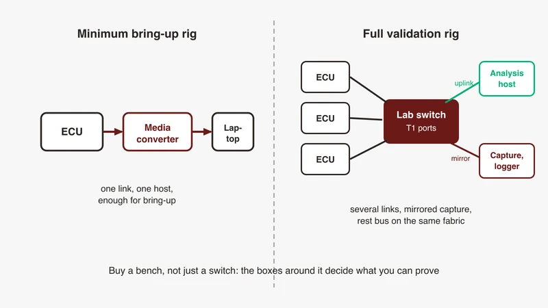
GSAS Micro Systems is an engineering partner, and on the T1 family that means one conversation before any equipment conversation: which physical layer classes your programme has to observe, and what your bench has to prove about each.
The practical questions are narrow. Are you validating link bring-up and roles, or traffic behaviour above a link that already works? Does a multidrop segment with PLCA appear in your topology, because a shared medium needs a different observation approach from a point-to-point link? Does your reach budget sit inside the link segment the PHY was specified against, connector count included? Worth settling before anything is quoted.
Our engineers work in IST, so a session lands inside your day, and quotations are issued in INR through the procurement channels Indian OEMs and tier-one suppliers already use. Teams we work with sit in Bengaluru, Pune, Chennai and Hyderabad. Start with the automotive Ethernet capabilities page, and request a scoped conversation to talk through a specific link, harness or validation plan. Where our answer is that you do not need to buy anything yet, that is the answer you get.
References
- IEEE 802.3 Ethernet Working Group: https://www.ieee802.org/3/
- IEEE P802.3bw 100BASE-T1 Task Force objectives (single balanced twisted pair, BroadR-Reach electrical interoperability, full duplex only, BER 10 to the minus 10, sub-100 ms fast startup, link segment with up to four inline connectors for at least 15 m): https://www.ieee802.org/3/bw/public/20140717_V3_Objectives.pdf
- IEEE P802.3bw D1.2 approved working group ballot comments (Clause 96, 66.666 MBd ternary symbols from 4B3B, PAM3 modulation, FORCE mode master/slave, rejected request for negotiable master/slave, link segment of up to 15 m with up to four inline connectors and two end connectors, single pair UTP): https://www.ieee802.org/3/bw/comments/8023bw_D1_2_approved.pdf
- IEEE P802.3bp 1000BASE-T1 Task Force updated objectives (full duplex only, BER 10 to the minus 10, automotive link segment at least 15 m with up to four inline connectors, optional segment goal of at least 40 m, optional single-pair auto-negotiation): https://www.ieee802.org/3/bp/Updated_Objectives_0714.pdf
- IEEE P802.3bp D1.4 Clause 97 draft text (link segment Type A unshielded balanced copper at least 15 m, Type B balanced copper at least 40 m, PAM3 at 750 MBd, 81B coding, 396-bit Reed Solomon FEC, MASTER and SLAVE clock roles, role set by auto-negotiation or by management or hardware configuration): https://www.ieee802.org/3/bp/public/may15/tu_3bp_02a_0515.pdf
- IEEE 802.3 public presentation, xBASE-T1 Auto-Negotiation (Clause 98 base page contents including 100BASE-T1 ability, 1000BASE-T1 ability and master/slave configuration; completes in under 1 ms): https://www.ieee802.org/3/cg/public/Jan2017/McClellan_10SPE_01_0117%20xBASE-T1%20Autoneg.pdf
- IEEE P802.3cg 10 Mb/s Single Pair Task Force objectives (15 m link segment with up to four inline connectors, 25 m mixing segment with at least 8 nodes, 1 km link segment with up to 10 inline connectors, BER values per segment, optional single-pair auto-negotiation, optional power distribution): https://www.ieee802.org/3/cg/objectives_3cg_0318.pdf
- IEEE P802.3cg Task Force public area (IEEE Std 802.3cg-2019 approved 7 November 2019): https://www.ieee802.org/3/cg/
- IEEE P802.3cg tutorial, “10Mb/s Single Pair Ethernet: A guide” (10BASE-T1L Clause 146 at 7.5 MBd PAM-3 4B3T with 1000 m reach on 18 AWG; 10BASE-T1S Clause 147 at 12.5 MBd 4B/5B DME; optional Clause 98 auto-negotiation defined only for point to point; PLCA beacon and transmit opportunity behaviour): https://www.ieee802.org/3/cg/public/Jan2019/Tutorial_cg_0119_final.pdf
- IEEE P802.3cg Clause 148 proposed draft text, PLCA Reconciliation Sublayer (node ID set by management, round-robin transmit opportunities, BEACON from node ID 0, half duplex only, enable and disable via management interface, Clause 22 behaviour when disabled): https://www.ieee802.org/3/cg/public/Sept2018/beruto_04_Cl_148_d2p0_proposed.pdf
- IEEE Std 802.3cg-2019 record, IEEE SA (title and scope): https://standards.ieee.org/ieee/802.3cg/7308/
- IEEE P802.3ch Multi-Gig Automotive Task Force objectives (2.5, 5 and 10 Gb/s, full duplex only, BER 10 to the minus 12, at least 15 m with up to four inline connectors on at least one type of automotive cabling, optional Clause 104 power over data lines): https://www.ieee802.org/3/ch/0317_approved_objectives_3NGAUTO.pdf
- IEEE P802.3ch Task Force public area (IEEE Std 802.3ch-2020 approved 4 June 2020): https://www.ieee802.org/3/ch/
- IEEE P802.3ch ad hoc, “Editorial status of shielding in draft” (Clause 149 link segment text describing a single shielded balanced pair of conductors, cable or backplane; coupling and screening attenuation qualified to where shielded balanced pair cabling is used): https://grouper.ieee.org/groups/802/3/ch/public/adhoc/zimmerman_3chah_01_010820.pdf
- IEEE P802.3ch D1.2 comments with final responses (Clause 149 MultiGBASE-T1, PAM4 data with PAM2 training, 10GBASE-T1 symbol clock relationship at 5625 MHz): https://grouper.ieee.org/groups/802/3/ch/comments/P8023ch_D1p2_comments_by_Comment_ID_final_responses.pdf
- IEEE P802.3cy Task Force approved updated objectives (25 Gb/s, full duplex only, BER 10 to the minus 12, at least 11 m with up to two inline connectors): https://www.ieee802.org/3/cy/P802d3cy_OBJ_UPDATED_APPROVED_07_14_22.pdf
- IEEE P802.3cy D2.0 initial working group ballot comments (25GBASE-T1 full duplex over a single shielded balanced pair, 14.0625 GBd): https://www.ieee802.org/3/cy/comments/802d3cy_D2_0_WIP-20220816.pdf
- IEEE P802.3cy D2.1 ballot comments (Clause 165, PAM2 to PAM4 switch on a PHY frame boundary): https://grouper.ieee.org/groups/802/3/cy/comments/802d3cy_D2_1_received_updated_091922.pdf
- IEEE Std 802.3cy-2023 record, IEEE SA (25 Gb/s on a single balanced pair of conductors suitable for automotive applications): https://standards.ieee.org/ieee/802.3cy/10280/
- IEEE P802.3dm Asymmetrical Electrical Automotive Ethernet Task Force public area: https://www.ieee802.org/3/dm/
- “Testing PAM4 Signaling for 10GBASE-T1 Automotive Ethernet”, Ethernet and IP at Automotive Technology Week 2021, hosted by IEEE SA (standard, clause, bit rate and baud rate mapping across the T1 family): https://standards.ieee.org/wp-content/uploads/import/documents/other/eipatd-presentations/2021/d2-06.pdf
- OPEN Alliance BroadR-Reach automotive specification v3.0, hosted on the IEEE 802.3 site: http://www.ieee802.org/3/1TPCESG/public/BroadR_Reach_Automotive_Spec_V3.0.pdf
- OPEN Alliance automotive Ethernet specification index (10BASE-T1S PLCA conformance test suite and management registers, half-duplex interoperability test suite, PMA compliance, sleep and wake-up; 1000BASE-T1 channel and component requirements in STP and UTP variants; MultiGBASE-T1 test material): https://opensig.org/automotive-ethernet-specifications/
- OPEN Alliance Technical Committees (TC14 interoperability and compliance tests for 10BASE-T1S PHYs; TC15 multi-gig interoperability and compliance tests): https://opensig.org/tech-committees/
- Linux ethtool manual page (master-slave values preferred-master, preferred-slave, forced-master, forced-slave; TX_TCLK sourcing in MASTER and SLAVE roles): https://man7.org/linux/man-pages/man8/ethtool.8.html
- Linux kernel ethtool netlink documentation (ETHTOOL_A_LINKMODES_MASTER_SLAVE_CFG, ETHTOOL_A_LINKMODES_MASTER_SLAVE_STATE, ETHTOOL_A_LINKSTATE_SQI): https://docs.kernel.org/networking/ethtool-netlink.html
Also appears in:
Building for Automotive & Mobility?
Talk to our application engineers for personalized tool recommendations.