In short
OPEN Alliance TC8 publishes the Automotive Ethernet ECU Test Specification as three public documents for 100BASE-T1, Layer 1, Layer 2 and Layer 3-7, plus a 1000BASE-T1 Layer 1 document at version 1.1. Its stated remit spans all seven OSI layers, and the published application-layer scope is SOME/IP and SOME/IP service discovery, covering both the DUT's own SOME/IP server behaviour and a defined Enhanced Testability Service test stub. Network management, diagnostics over IP and end-to-end time synchronisation accuracy are not test groups in those documents, so a requirement that names them needs deliberate coverage in a test plan of your own.
Ask three engineers what OPEN Alliance TC8 covers and you get “layers 1 to 4”, “the whole stack” and “the PHY tests”. The first is wrong, the second is a committee statement rather than a document, and the third is one chapter of one document. All three get written into requirement documents, and the gap between them is where a programme discovers in month nine that nobody owns service discovery testing.
The documents are public. This is what they enumerate, where their boundary sits, and what a plan of your own has to cover above it. If the technology itself is new to you, start with our complete guide to automotive Ethernet.
What TC8 is, in one paragraph
The committee, and the documents it publishes
The OPEN Alliance runs numbered technical committees. TC8’s own page describes it as responsible for developing and upholding Automotive Ethernet ECU Test and Conformance Specifications throughout all seven OSI layers, with the objective of a unified foundation for ECU conformance qualification, and adds that TC8 also outlines the test processes and requirements that let qualified test houses exist.
That is the remit. The deliverables are narrower. The public register lists four test documents plus a process document:
- Automotive Ethernet ECU Test Specification Layer 1 (100BASE-T1), version 3.0
- Automotive Ethernet ECU Test Specification Layer 2, version 3.0
- Automotive Ethernet ECU Test Specifications Version 3.0, Layer 3-7
- 1000BASE-T1 Ethernet ECU Test Specification Layer 1, version 1.1
- Test Process, ECU and Network test, version 1.0
The committee roadmap on the TC8 page still shows that last test document, the 1000BASE-T1 Layer 1 specification, as pending. That mismatch is the reason to read the register rather than any summary, including this one.
What a TC8 pass certifies, and what it does not
The Layer 3-7 document states its claim in the introduction: successful execution and passing of all relevant tests gives a device under test a minimum approval that the device’s basic implementations are done correctly. Minimum approval that basics are correct. Not that the ECU works, not that it fits your architecture, not that it will interoperate with the node it has to talk to.
The Test Process document reinforces that by defining two categories: an ECU test, performable without involving other ECUs, and a network test, whose precondition is that every ECU has already passed its ECU test. TC8’s specification is the first, and this article is about the space after it.
The OPEN Alliance specifications you will be asked about
| Specification | Scope, in one line | Who it applies to |
|---|---|---|
| TC8, ECU test specification | Conformance and interoperability test cases for an ECU’s Ethernet behaviour, published as Layer 1, Layer 2 and Layer 3-7 documents | Any ECU with an automotive Ethernet port |
| TC10, sleep and wake-up | Controlled link shutdown and wake-up over the pair, including wake forwarding | Any node in a partial networking architecture |
| TC13, PHY test house qualification (committee, no published document) | Methodology and round-robin comparison so PHY test reports from different houses are equivalent | Background only; the requirements you are held to are in the TC8 Test Process document |
| TC14, 10BASE-T1S | Conformance, interoperability and EMC test specifications for 10BASE-T1S PHYs | Multidrop 10 Mbit/s segments only |
TC10, sleep and wake-up behaviour on the link
TC10 publishes specifications, not released test suites. Its stated goals cover fast wake-up and wake-up request forwarding for a global wake on layer 1, controlled link shutdown to hibernate parts of a network, a global wake-up time requirement, an electrical interface for wake and sleep, and compliance with AUTOSAR network management, across 10BASE-T1S through Multi-G. The roadmap on the same page lists the 100BASE-T1, 1000BASE-T1 and MultiGBASE-T1 sleep and wake-up test suites as pending, so TC10 behaviour is verified against the specification and the OEM’s requirement, not against a released test suite. Our TC10 article covers the handshake, the timers and the ways a wake fails to arrive. The one place TC8 touches it is Layer 1, whose third link-up trigger cycle is a wake-up of the device.
TC14, and how to read the register rather than a blog list
TC14 covers interoperability and compliance tests for 10BASE-T1S PHYs, the 10 Mbit/s multidrop member of the T1 family. Its stated goal is to enable 10BASE-T1S in an automotive context: conformance, interoperability and EMC test specifications, advanced diagnostic features, a system implementation specification, a PMD transceiver interface, PLCA registers and topology discovery. If your links are point to point 100BASE-T1 or 1000BASE-T1, TC14 is not your document.
Registers move: the same specification appeared as pending on one committee page and as a released version 1.1 on the register. Before citing a version in a requirement document, read the version and date next to the title on the register itself.
How the TC8 suite is structured
Layer 1: interoperability cases and PMA conformance
The Layer 1 document for 100BASE-T1 splits into two chapters, and the split is the conformance versus interoperability story in miniature.
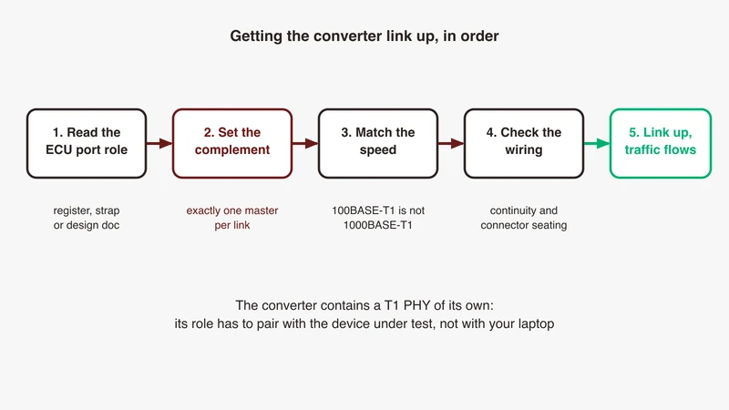
Chapter 5.1 is titled Interoperability Tests: link-up time across three trigger cycles (power on the link partner, power on the device, wake the device), indicated signal quality on channels with decreasing and increasing quality, and cable diagnostics for near and far end open and short. Behavioural cases, all needing a link partner. Chapter 5.2 is PMA: transmitter electrical specifications and a transmitter distortion test, measurements against numbers taken with calibrated instrumentation, needing no partner at all. If a link simply fails to come up on your bench, that is neither test; our 100BASE-T1 link-up checklist is where to start.
Layer 2: switching, VLAN and MAC level behaviour
The Layer 2 document scopes itself to the data link layer, and in practice to the switch inside an ECU. It defines the device under test as the logical automotive Ethernet switch entity, including software and configuration living in an MCU on the same ECU, and assumes the switch silicon and PHYs were verified elsewhere. This is a test of your configuration, not your vendor’s part.
The functional groups are VLAN testing, general, address learning, filtering of incoming frames, time synchronisation, quality of service and configuration. Identifiers show the shape: SWITCH_GEN_001 store and forward operation, SWITCH_ADDR_007 positive address ageing, SWITCH_ADDR_013 address table overflow reporting, SWITCH_FILT_007 ingress rate limitation, SWITCH_QOS_004 rate based traffic shaping, SWITCH_CONF_001 starting in do-not-forward mode.
The detail that changes how you prepare: the VLAN cases are written against “the customer’s VLAN requirements”. If that requirement is ambiguous, so is the test, and the lab cannot resolve it for you. Bench hardware for those cases is covered in our lab switch guide.
Layer 3-7: IP, transport, and the application chapter
The Layer 3-7 document declares two scopes: a TCP/IP protocol family scope covering layer 3 network and layer 4 transport, and an automotive protocols scope covering layers 5, 6 and 7, named as SOME/IP and SD. The chapters, with page ranges in version 3.0, give an honest sense of weight:
| Chapter | Pages | What it exercises |
|---|---|---|
| ARP | 43 to 84 | Request and reply handling, malformed and conflicting entries |
| ICMPv4 | 84 to 99 | Type and error message handling |
| IPv4 | 99 to 139 | Header, version, TTL, checksum, addressing, fragments, reassembly |
| Dynamic IPv4 link-local | 139 to 190 | Address selection, conflict detection and defence |
| UDP | 190 to 225 | Header fields, user interface behaviour |
| DHCPv4 client | 225 to 293 | Initialisation, allocation, request construction, reacquisition |
| TCP | 293 to 413 | Basics, header, flags, sequence, MSS options, out of order, closing |
| SOME/IP | 413 onward | Message format, on-wire identifiers, RPC, service discovery entries |
The TCP chapter is 120 pages of state machine behaviour. If your stack is an established implementation with a long field history, much of it is a formality. If someone wrote a lightweight stack to save flash, that is where the programme finds out.
The SOME/IP chapter and the Enhanced Testability Service
This is the part one-paragraph summaries leave out. The SOME/IP chapter is written against the AUTOSAR service discovery and serialisation specifications, and its coverage table maps clauses to test identifiers: message format, the options array, find service, offer service, stop offer, subscribe eventgroup, subscribe acknowledgement and negative acknowledgement entries, startup behaviour, server answer behaviour, identifier definitions, and the mapping of addresses and ports for responses and error messages. Our SOME/IP explainer covers those structures on the wire.
To make that testable, TC8 defines a stub. The Enhanced Testability Service, or ETS, exists on the reasoning that defined interfaces are needed to test SOME/IP and that generic tools require the interface to be standardised. It addresses the service discovery, serialisation, remote procedure call and publish/subscribe parts of the stack, across positive, negative, load and regression categories. Its methods are ordinary SOME/IP methods with fixed identifiers: resetInterface, suspendInterface to force the device to stop offering and reoffer after a stated delay, checkByteOrder, echo methods for datatypes and bitfields, and clientServiceActivate and clientServiceSubscribeEventgroup to drive the device as a client.
That is the mechanism and it is also the boundary. TC8 tests SOME/IP protocol behaviour, on the device’s own server in one set of cases and through a service it defines in another. It does not test your services.
Where TC8 stops, and what lives above it
Draw the coverage boundary on a stack diagram and it does not sit neatly between layer 4 and layer 5. It cuts sideways through the application layer: SOME/IP protocol behaviour is inside, everything else at layers 5 to 7 is outside.
Service discovery beyond the stub. TC8 checks that your stack forms and answers SD entries correctly. It does not check that your ECU offers the right service and instance identifiers, with the right eventgroups, at the right point in startup, or that a client finds them. Our service not available debugging guide separates the discovery, routing and transport causes; seeing any of it in a capture takes configuration of its own, covered in the Wireshark SOME/IP fix list and the payload decode guide.
Network management. There is no network management test group in the Layer 3-7 document. AUTOSAR UDP-NM modes, state transitions and the timers that decide which node holds a cluster awake are absent from the suite and present in the requirement document. Our ECU testing over Ethernet article treats network management as a first class lifecycle test target, which is where it has to be treated.
Diagnostics over IP. ISO 13400 is not a TC8 scope at all. Vehicle discovery, routing activation and the diagnostic message phase each need their own cases, and the DoIP explainer sets out the three phases to write them against.
Time synchronisation. Layer 2 contains exactly one time synchronisation case, SWITCH_TIME_001. It checks that time information leaving a bridge’s master ports is not distorted by interfering traffic: load the ports to 80 to 90 percent of line rate with 1500 byte frames, ingress timestamp the time synchronisation traffic for at least 300 seconds, reconstruct protocol time from one-step Sync messages and two-step Sync and Follow_Up pairs, and require the differences to stay within plus or minus 200 nanoseconds per time domain. That is a bridge behaviour test, not a measurement of end to end time error at a slave, and it says nothing about grandmaster failover or path asymmetry. Proving 802.1AS works is a separate exercise; when the domain will not form at all, gPTP troubleshooting comes first.
Testing the application layers: a practical coverage plan
The useful thing about ETS is not that you will implement it. It is that it shows what a testable service looks like: a way to reset state, a way to force a stop offer and a timed reoffer, a way to make the device act as a client on demand, and a way to read back the last value received on the reliable, unreliable unicast and multicast paths. Build those four affordances into your application and your service level tests stop depending on power cycling.
Two shapes of case are worth writing early. Service discovery negatives: offer with a wrong instance identifier, subscribe to an eventgroup that is not offered, suspend the offer mid-session and check the client’s re-find timing. Large payloads: one exceeding the path MTU on the unreliable path, exercising IPv4 fragmentation and reassembly (which TC8 tests) alongside your application’s segmentation policy (which it does not).
| Layer | Representative test | Pass evidence | Who usually runs it |
|---|---|---|---|
| Physical | Link-up time, wake trigger | Time from stimulus to link, spread across repeats | In-house bench or test house; needs a link partner and a controlled supply, not calibrated metrology |
| Physical (PMA) | Transmitter distortion | Measurement against the PMA limits | Test house, with calibrated instrumentation |
| MAC and VLAN | Untagged frame forwarding per OEM VLAN table | Frame received only on expected ports | Test house or in-house switch bench |
| IP and transport | Fragment reassembly, TCP closing sequence | Capture showing correct state transitions | In-house bench is realistic here |
| SOME/IP protocol | SD entry format, offer and subscribe behaviour | Annotated capture against the AUTOSAR clause | Test house via ETS, in-house via your own stub |
| Your services | Offer, find, subscribe on your real catalogue | Capture plus interface description cross-check | In-house, always |
| Network management | Cluster stays awake, then releases | Full lifecycle capture through to bus sleep | In-house, then vehicle |
Correlating this with the CAN and LIN traffic around it is covered in the multi-bus capture guide, and getting a clean copy of in-vehicle traffic under taps and mirror ports.
Conformance versus interoperability, and why both are in your plan
The suite already splits them
TC8 draws the line inside its own documents. Layer 1 chapter 5.1 is titled Interoperability Tests and needs a link partner; chapter 5.2 is PMA and needs an instrument. The Test Process glossary defines a test case as one by which the manufacturer demonstrates compliance to a particular aspect of the specifications, or interoperability with another OPEN Alliance product. Two demonstrations, one sentence.
A passing device can still fail against a partner node
Conformance asks whether the device matches the document. Interoperability asks whether it works against a specific other device. They diverge whenever the document permits a choice, whenever two implementations read an ambiguous clause differently, and whenever a parameter such as a VLAN table or a service identifier comes from your project rather than the specification.
The OPEN Alliance treats that as a real risk. The Test Process document requires each test house to validate every test case against a reference system or golden device, then to run at least one improvement activity on top: exchanging reference systems between test houses in a plugfest, on the reasoning that differing results reveal test case implementation bugs and setup errors, or passing a device to a second test house to compare results. Two accredited labs running the same suite against the same device are expected to be able to disagree. Assume the same of your ECU and your partner’s.
Pairwise testing when you cannot test against every peer
Rank the peers instead of attempting a matrix. Test against the node that shares the most link segments with you, the node with the least mature stack, the node from a different supplier and silicon family, and the node with the tightest timing dependency on you. Four pairings cover more real risk than a matrix nobody finishes, and each wants a capture on both sides at the same time.
Where no peer exists yet, a simulated one is the honest substitute. Our companion article on rest bus simulation for Ethernet vehicles covers building the residual network in software, including the caveat that a simulated peer inherits your reading of the interface description and cannot disagree with it.
Who runs which tests
| Setting | Good for | Weak at |
|---|---|---|
| In-house bench | Protocol behaviour, regression, lifecycle and negative cases, finding defects cheaply and often | Anything needing calibrated fixtures, traceable measurement or an accredited report |
| Third-party test house | Layer 1 electrical measurement, a report an OEM will accept, comparability between suppliers | Your architecture-specific behaviour, which it has no requirement document for |
| OEM network integration | Interactions between ECUs, load, real harness, real wake paths | Isolating which supplier caused it |
The TC8 Test Process document sets the bar for the middle column. A test house must be ISO 17025 accredited, with validated methods, uncertainty estimation, traceability to primary standards and records kept for ten years. It must be neutral: independent of the OEM, of the supply chain, and economically. It must show automotive Ethernet experience at layer 1 and above it, and hold OPEN Alliance technical membership with active TC8 participation. UNH-IOL, the independent laboratory at the University of New Hampshire, publicly identifies itself as an OPEN Alliance approved test laboratory and lists automotive Ethernet test services across 10BASE-T1S, 100BASE-T1, 1000BASE-T1 and MultiGBASE-T1.
What to bring so the first round is not wasted
The lab issues a DUT information questionnaire, the manufacturer fills it in, the lab builds the test plan from it, then the device arrives and execution starts. Everything that determines your pass rate happens before the device ships.
Bring the questionnaire completed by someone who has read the configuration, not the datasheet. Bring the VLAN table and priority mapping as the OEM specified them, because the Layer 2 cases are written against your requirements. Bring the service interface description, a way to hold the device in a known state and reset it without a power cycle, the version of every document you are claiming against, and your own pre-compliance defect list.
Reading a report
In our experience, failures against a numeric limit such as a PMA measurement point at the device, while failures in behavioural groups such as address ageing or TCP closing more often point at configuration. Failures appearing once, or on one port only, deserve a question about the setup first: the suite’s own process assumes benches have bugs, which is why reference systems get exchanged.
The India picture
A Tier-1 in Pune, Chennai or Bengaluru is typically asked for three things. A TC8 report against named document versions, with the applied test groups listed. Evidence for TC10 behaviour against the specification and the OEM’s wake and quiescent current requirement, since no released public TC10 test suite exists to point at. And project specific evidence for whatever the requirement document adds above the suite: service discovery against the interface description, network management timing, diagnostics over IP, time synchronisation accuracy. The third bucket is where programmes lose time, because it has no suite to hide behind.
The query “automotive Ethernet conformance test lab India” deserves a straight answer. Accredited conformance testing is carried out by test houses meeting the ISO 17025 and neutrality requirements set out in the TC8 process document, and the report your OEM accepts comes from one of those. What a team in India can build locally is the pre-compliance bench that makes the external round short: protocol behaviour, negatives, lifecycle, captures. The vehicle architecture context and physical layer capture on the bench are worth reading if you are scoping one from scratch.
Building it is mostly not a purchasing decision. It is deciding which published test groups you can genuinely stimulate, writing the cases, and running them on every build. The Test Process document makes the same point: test at the earliest possible time when new features are introduced, with a regression run before start of production.
Where GSAS fits
GSAS Micro Systems is an engineering partner to automotive teams working on Ethernet based architectures, with applications engineers in Bengaluru, Pune, Chennai and Hyderabad. On conformance work the useful conversation is a scoping one: which published TC8 test groups your bench can realistically exercise, what belongs at an accredited test house, and which requirements in your OEM’s document have no suite behind them at all.
The second conversation is a review. A test plan often covers the suite well and stops at the boundary described above, with service discovery, network management, diagnostics over IP and time synchronisation accuracy either unassigned or assumed to be somebody else’s. Reading an existing plan against the published documents and marking the gap takes a short engagement, and tends to change the schedule more than any tool decision.
We support pre-compliance bench preparation; certification itself is carried out by accredited test houses. If either conversation is useful, our automotive Ethernet capabilities page sets out what we cover, and you can request a scoping discussion with our applications team.
References
- OPEN Alliance specification register: opensig.org/automotive-ethernet-specifications
- OPEN Alliance TC8 committee page: tc8-automotive-ethernet-ecu-test-specification
- ECU Test Specification Layer 1, 100BASE-T1, v3.0: public PDF
- ECU Test Specification Layer 2 v3.0: public PDF
- ECU Test Specification Layer 3-7 v3.0: public PDF
- Test Process, ECU and Network test v1.0: public PDF
- OPEN Alliance TC10 committee page: tc10-automotive-ethernet-sleep-wake-up
- OPEN Alliance TC14 committee page: tc14-interoperability-compliance-tests-for-10base-t1s-phys
- OPEN Alliance TC13 committee page: tc13-new-test-house-qualification-requirements
- UNH-IOL automotive Ethernet testing services: iol.unh.edu/testing/ethernet/ae
- AUTOSAR, Specification of Service Discovery V1.2.0 R4.1 Rev 3 and Example for a Serialization Protocol (SOME/IP) V1.1.0 R4.1 Rev 3, the two documents the Layer 3-7 SOME/IP coverage table cites, reachable from the AUTOSAR standards index: autosar.org/standards/foundation
- IEEE 802.3 Ethernet Working Group: ieee802.org/3
Also appears in:
Building for Automotive & Mobility?
Talk to our application engineers for personalized tool recommendations.