
In short
gPTP sync usually fails on Linux for three reasons. Hardware timestamping is not actually in use, so check ethtool -T for a real PTP Hardware Clock index and a receive filter that covers layer 2 PTP. ptp4l is not in the 802.1AS transport mode, so its config needs network_transport L2, delay_mechanism P2P and transportSpecific 0x1, and phc2sys and pmc have to send the same transportSpecific value or ptp4l drops their management messages and phc2sys prints Waiting for ptp4l forever. Or the TAI to UTC offset was never set, so the clocks lock cleanly and the wall clock is still wrong.
Search for gPTP troubleshooting and the results are mostly about racks: boundary clock switches, UDP transport, a domain number you set once and forget. Follow that on a vehicle bench and you get a daemon that starts cleanly, logs that look almost right, and a domain that never forms.
802.1AS constrains PTP in ways that change the Linux command line. Below are the four failure shapes we see on automotive Ethernet benches. Proving the sync you end up with, as a number with a method, is a separate exercise. Every option, default and log string traces to a source in the References.
gPTP is not just PTP with a different name
What IEEE 802.1AS constrains compared with general-purpose PTP
The TSN Documentation Project for Linux puts it plainly: gPTP is a profile from IEEE 1588 that “consists of simplifications and constraints to PTP to optimize it to time-sensitive applications”, using 1588 in the IEEE 802.1 working group’s words “where applicable in the context of IEEE Std 802.1Q”. The current base standard is IEEE Std 802.1AS-2025, with 802.1DG-2025 as the automotive profile. For the wider TSN picture, see our automotive Ethernet guide.
Peer delay only, and layer 2 transport
Three constraints do most of the damage when you carry data centre habits across.
Transport is layer 2. The ptp4l default is UDPv4. The linuxptp gPTP example config sets network_transport L2 and ptp_dst_mac 01:80:C2:00:00:0E.
Delay measurement is peer delay. The ptp4l default is E2E; gPTP uses P2P, and every clock on one communication path must use the same mechanism.
transportSpecific is not zero. ptp4l documents it as “the transport specific field”, range 0 to 255, default 0. gPTP.cfg sets 0x1, and that field is behind a startup failure that produces no error on either side.
Every device in the path must be time aware, and what happens when one is not
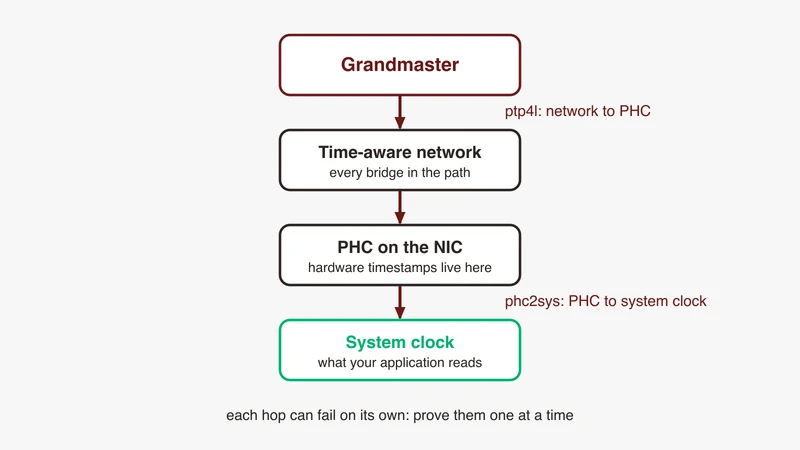
Peer delay is hop by hop: each port measures delay to its immediate neighbour, and a participating bridge accounts for the time a frame spends inside it. One that does not participate adds delay nobody measures, which lands in the offset as error that varies with load.
On a Linux bench there is a harder stop. The gPTP destination MAC is link-local reserved, and the iproute2 manual documents group_fwd_mask as the bitmask deciding whether to forward “frames destined to link-local addresses, ie addresses of the form 01:80:C2:00:00:0X (defaults to 0, ie the bridge does not forward any link-local frames)”.
Why generic PTP tutorials send you down the wrong path
A data centre guide puts you on UDP, with E2E delay, and transportSpecific at its default. All three are wrong for 802.1AS, and none produces an error. ptp4l is doing what you configured. It is just not in the domain.
The Linux stack, and how to prove each layer works
The pieces: PHC on the NIC, ptp4l, phc2sys, system clock
The PTP hardware clock is a counter on the NIC. The kernel PHC documentation describes a class driver that “creates a character device for each registered clock”, and user space uses an open file descriptor on that character device as a POSIX clock id. ptp4l disciplines that PHC from the network. phc2sys is “a program which synchronizes two or more clocks in the system”, typically the system clock to a PHC that ptp4l is itself synchronizing.
Two hops, and most confused sessions blame one for a symptom on the other.
Confirming hardware timestamping is real, not software fallback
ethtool -T <iface> shows “the device’s time stamping capabilities and associated PTP hardware clock”. Read three things:
- Capabilities should list
hardware-transmit,hardware-receiveandhardware-raw-clock, theSOF_TIMESTAMPING_*_HARDWAREflags. - PTP Hardware Clock must print an index. ethtool prints
nonewhen the driver reports a negative index. - Hardware Receive Filter Modes must cover layer 2 PTP:
ptpv2-l2-event (HWTSTAMP_FILTER_PTP_V2_L2_EVENT), or the broaderptpv2-eventorall.
That last line is where the data centre assumption bites hardest: ptpv2-l4-event is enough for a rack and useless for a vehicle. The kernel documentation adds that “hardware time stamping must also be initialized for each device driver that is expected to do hardware time stamping”, so a capability line describes silicon, not what the driver enabled.
Reading the PHC directly before you trust any daemon output
phc_ctl is “a program which can be used to directly control a PHC clock device”, intended for debugging: get reads the time, cmp compares the PHC to CLOCK_REALTIME, caps shows capabilities. The manual warns these “may have adverse side effects on running instances of ptp4l or phc2sys”, so use only the read-only ones while the daemons are up.
The four log lines that tell you where you are
Run both daemons with -m and read for these.
Port state transitions, as <port>: <old state> to <new state> on <event>. A port that never leaves LISTENING is the whole diagnosis for Failure 2.
Role selection: selected best master clock <id>, selected local clock <id> as best master, or assuming the grand master role. If none appears, nothing owns the time.
The offset line: master offset <ns> s<state> freq <ppb> path delay <ns>. That is ptp4l’s line. phc2sys prints its own, CLOCK_REALTIME phc offset <ns> s<state> freq <ppb> delay <ns>, with the same servo digit. The s digit is the servo state, and the linuxptp enum runs SERVO_UNLOCKED, SERVO_JUMP, SERVO_LOCKED, SERVO_LOCKED_STABLE, so s0 is not tracking, s2 is locked, s3 is stable. s3 only ever appears when servo_offset_threshold is non-zero; it is 0 by default and unset in gPTP.cfg, and automotive-slave.cfg is where linuxptp sets it (30, with servo_num_offset_values 10).
UTC offset updates: updating UTC offset to <n>, whose absence is a clue for Failure 3.
Failure 1: phc2sys sits at “Waiting for ptp4l”
What the message means: phc2sys is waiting for a port to reach a usable state
A public issue filed against the Avnu TSN documentation project records the symptom exactly, phc2sys[1374.742]: Waiting for ptp4l... repeating and never clearing, with no resolution in the thread. The cause has to be read out of the two processes, not the message.
The string appears twice in phc2sys.c: once when a default data set query times out, once when run_pmc_wait_sync finds no usable port. That function in pmc_agent.c returns success only when a queried portState is PS_MASTER or PS_SLAVE, matching the manual, where phc2sys “waits for ptp4l to get at least one port in server or client mode”. The message is about a conversation between two processes, not about clocks.
The gPTP transport mode option that phc2sys needs in an 802.1AS domain
phc2sys talks to ptp4l with PTP management messages over a UNIX domain socket. In pmc_agent.c, init_pmc_node builds that client with config_get_int(cfg, NULL, "transportSpecific") << 4, and the shifted value lands in the message header byte.
ptp4l filters on receive. port_ignore in port.c drops a message when an 802.1AS port sees a transport specific value that is neither the 802.1AS nor the common mean link delay service value, and again when match_transport_specific is set and the value does not match. The manual states the rule: “By default, incoming messages are dropped if their transportSpecific field does not match the configured value.”
Your gPTP config sets transportSpecific 0x1. phc2sys defaults to 0, so its messages get dropped, the query times out, and phc2sys waits forever while both processes look healthy.
The fix is one option: the phc2sys manual gives phc2sys -a -rr --transportSpecific=1 as the 802.1AS version of the preceding example, and the TSN Documentation Project states that the --transportSpecific option “is required when running phc2sys in a gPTP domain”. pmc takes it as -t, default 0x0, hence the documented pmc -u -b 0 -t 1 "SET ...".
Management interface access between the two daemons
If transportSpecific is right and the message persists, check the socket. ptp4l’s uds_address is “the address of the UNIX domain socket for receiving local management messages”, default /var/run/ptp4l in released versions, /var/run/ptp/ptp4l on current linuxptp master, which symlinks the two for compatibility; phc2sys points at it with -z, same default. Two ptp4l instances, a non-default path in one config file only, or a container boundary all do this. domainNumber must match too.
Checking whether ptp4l ever reached a client or server port state at all
Ask ptp4l directly instead of inferring from phc2sys:
pmc -u -b 0 -t 1 "GET PORT_DATA_SET"
pmc -u -b 0 -t 1 "GET TIME_STATUS_NP"
pmc -u -b 0 -t 1 "GET TIME_PROPERTIES_DATA_SET"
If those return, you have a real port state problem. If they time out the way phc2sys does, the variables left are transportSpecific, domainNumber and the socket path.
Failure 2: no sync messages arrive
Layer 2 versus UDP transport, and the interface you actually bound to
network_transport defaults to UDPv4. If nothing says L2 or -2, you are sending IPv4 multicast into a network listening for 01:80:C2:00:00:0E. Both ends run; neither hears the other. Then check the interface: binding to the management NIC rather than the T1 one gives a daemon that looks healthy.
Priority marking that does nothing, and the reserved address a switch can filter
Priority handling is transport dependent: socket_priority “is only available with the IEEE 802.3 transport (the -2 option) and is silently ignored when using the UDP IPv4/6 network transports”. Mark gPTP for a priority queue while still on UDP and the marking does nothing, silently. On the switch side, a port that filters or reclassifies the reserved group address removes gPTP without disturbing anything else you would notice.
Capturing on a mirror port that strips or reorders the frames you need
A mirror can strip VLAN tags, reorder against the original egress, and timestamp on the capture host rather than at the wire. Fine for “did a Pdelay_Req ever appear”, useless for interval or jitter. When logs and capture disagree, measure at the wire.
Grandmaster election: nothing is claiming the role, or two things are
In plain gPTP the best master clock algorithm decides. If none of the three role lines above appears, no Announce messages are being exchanged, which is Failure 2 restated.
The Avnu automotive profile removes the election, optimising gPTP “to improve startup time and reduce network load”, the main difference being that “the BMCA is disabled so each device is statically assigned as master or slave”. In linuxptp that is BMCA noop plus serverOnly 1 in automotive-master.cfg and clientOnly 1 in automotive-slave.cfg, inhibit_announce 1 on both, and ignore_source_id on the client, which cannot otherwise identify the server in Sync and Follow_Up messages. Two static masters, or two configs that both say clientOnly, are how this goes wrong, and neither logs an election because there is none.
A quick capture that answers this in one minute
Filter on destination MAC rather than a protocol dissector, so a wrong EtherType or missing tag still shows up:
sudo tcpdump -i eth0 -e -nn ether dst 01:80:C2:00:00:0ENo frames means transport or interface. Pdelay with no Sync means peer delay works and nobody is grandmaster. Frames both ways with ptp4l still LISTENING means the daemon is discarding them.
Failure 3: it syncs, then drifts or jumps
Offset from master oscillating: pdelay asymmetry and cable delay assumptions
An offset swinging either side of zero usually means the delay being subtracted is wrong, not that the servo is badly tuned. neighborPropDelayThresh is the “upper limit for peer delay in nanoseconds. If the estimated peer delay is greater than this value the port is marked as not 802.1AS capable”, and min_neighbor_prop_delay is the matching lower limit. The gPTP example sets 800 and -20000000.
gPTP.cfg’s 800 ns is a tight window: ptp4l marks the port not 802.1AS capable rather than degrading gracefully when the estimated peer delay falls outside min_neighbor_prop_delay and neighborPropDelayThresh. On a real link the measured peer delay includes the PHY’s ingress and egress latency, not just cable propagation, so characterise it on your hardware before deciding the window is wrong. The other half is asymmetry: peer delay assumes both directions are equal. ingressLatency and egressLatency correct characterised hardware delay at each end, and delayAsymmetry is the option for a path whose two directions are not equal: ptp4l documents it as “the time difference in nanoseconds of the transmit and receive paths”, positive when the server-to-client propagation time is longer, default 0.
Clock rate ratio and neighbour rate ratio going unstable
Peer delay also produces a neighbour rate ratio, the estimate of how fast the neighbour’s clock runs relative to yours. linuxptp maintains it per port as an nrate estimator with a validity flag and warns when the timestamps feeding it are bad, so an unstable rate ratio and an unstable offset are usually one fault seen twice.
Watch freq too. sanity_freq_limit is “the maximum allowed frequency offset between uncorrected clock and the system monotonic clock in parts per billion”, beyond which “a warning message will be printed and the servo will be reset”.
TAI against UTC: the 37 second offset in force at time of writing, and how it is set at runtime
This is the failure where everything looks right and the wall clock is wrong. The phc2sys manual states it directly: “PTP time scale is continuous and shifted against UTC by a few tens of seconds as PTP time scale does not apply leap seconds”, and in hardware timestamping mode “PHC must follow PTP time scale while system clock follows UTC. Time offset between these two is maintained by phc2sys”. phc2sys takes that offset from ptp4l when -a or -w is in effect, or from -O. Nor does 802.1AS supply it: the revision scope notes that synchronization to an external signal such as UTC or TAI is not part of the standard.
On the grandmaster, the TSN Documentation Project sets it through ptp4l at runtime:
sudo pmc -u -b 0 -t 1 "SET GRANDMASTER_SETTINGS_NP clockClass 248 \
        clockAccuracy 0xfe offsetScaledLogVariance 0xffff \
        currentUtcOffset 37 leap61 0 leap59 0 currentUtcOffsetValid 1 \
        ptpTimescale 1 timeTraceable 1 frequencyTraceable 0 \
        timeSource 0xa0"
37 is the offset in force at time of writing, and it changes only when a leap second is declared. It is a configured value with a shelf life, not a protocol constant. The Avnu check_clocks tool makes the point: it carries #define UTC_OFFSET 37 directly under a comment reading “FIXME: Figure out the UTC_OFFSET programmatically so we don’t have to manually update it here everytime it changes.” It then checks the three places the value must land, one message each: “phc-rt delta is not 37 sec !”, “phc-tai delta is greater than 50 usec !”, and “TAI offset set in kernel is not correct !” when adjtimex disagrees.
The system clock is right and the PHC is wrong, or the reverse
In manual mode -s names the source and -c the sink, defaulting to CLOCK_REALTIME. In automatic mode -a follows the ptp4l port states, and the system clock is not synchronized at all “unless the -r option is also specified”, with -r twice making it eligible as a source. The trap is running -a alone and wondering why the system clock never moves.
Then confirm nothing else is fighting for it: timedatectl | grep NTP, then timedatectl set-ntp false. The same troubleshooting section flags NetworkManager resetting the NIC, and more than one instance of either daemon on the same clock.
Temperature and oscillator behaviour on a real ECU rather than a server NIC
On a config that sets servo_offset_threshold, a servo that held s3 on the bench and drops back to s2 or s0 in a chamber is tracking a real frequency change, which is why freq belongs in your log next to the offset.
The other effect is not the oscillator. Mechanisms that idle the CPU, NIC or the PCIe bus can take “100 µs or more until they are fully active again”, and in that state “phc2sys might report timeouts or you might measure a large difference between System clock and PHC even though phc2sys reports only small offsets”. The documented mitigation is Intel TCC mode where the BIOS offers it, and failing that disabling PCIe ASPM (echo performance > /sys/module/pcie_aspm/parameters/policy). On an ECU with an aggressive sleep policy, rule that out before suspecting the crystal.
Failure 4: it works point to point and breaks across the network
A non time aware bridge in the path, and how to find it
Two nodes back to back sync; put a switch between them and it stops. Bisect: run tcpdump ether dst 01:80:C2:00:00:0E on both sides of each candidate. A device that receives gPTP and emits none is not forwarding it. One that forwards it unchanged, with no correction applied, is treating it as ordinary traffic, which is worse than dropping it because the domain forms and is quietly wrong.
assume_two_step covers a related problem: “treat one-step responses as two-step if enabled. It is used to work around buggy 802.1AS switches”. gPTP.cfg enables it, which says something about how often bridges get this wrong.
Residence time and hop count budgets
Each time-aware bridge measures how long a Sync spends inside it and adds that to the accumulated correction, so error accumulates along the chain, hop by hop, plus each device’s timestamping granularity. The public sources cited here publish no hop limit or residence time figure, and we are not going to invent one. Take it from your timing requirement and your switch vendor’s characterisation. Where the path runs through zonal and domain controllers, those are the hops that count.
Scheduling interactions worth knowing about
Time-aware scheduling depends on gPTP, and the setup order is easy to get backwards. The TSN Documentation Project states the rule: qdisc setup resets the NIC and can put ptp4l out of sync, so if it happens after the clocks are synchronised, repeat the synchronisation steps and verify again. That failure is intermittent by boot order, not by configuration, so it survives a review of the config files.
Redundancy and multiple domains, when the vehicle design uses them
For more than one gPTP domain or ptp4l instance, -z “can be used up to 16 times in the automatic mode to synchronize clocks between multiple ptp4l instances”, and -n up to 16 times for the matching domain numbers, in command line order. Get the pairing right, or you get Failure 1 on the instance you were not thinking about.
Symptom to cause table, with the command that confirms it
Table: symptom, likely cause, command or capture that confirms, fix
| Symptom | Likely cause | Confirm with | Fix |
|---|---|---|---|
Waiting for ptp4l... repeats | transportSpecific mismatch | pmc ... -t 1 "GET PORT_DATA_SET" works, -t 0 does not | Add --transportSpecific=1 |
| Same, and pmc also times out | Wrong uds_address or domainNumber | ss -x; compare both config files | Align socket path and domain |
| ptp4l stuck LISTENING, no frames | UDP transport, or wrong interface | tcpdump ether dst 01:80:C2:00:00:0E | network_transport L2, fix -i |
| Pdelay seen, no Sync, no role line | Nothing is grandmaster | grep log for grand master role | serverOnly on master, or enable BMCA |
| Port marked not 802.1AS capable | Peer delay outside the window | ptp4l log vs neighborPropDelayThresh | Set thresholds for the real harness |
Offset oscillates, never reaches s2 | Asymmetric peer delay | master offset ... path delay over time | Fix path; set delayAsymmetry, or ingressLatency/egressLatency for characterised hardware delay |
s2 reached, wall clock 37 s out | TAI to UTC offset never set | check_clocks, or phc_ctl /dev/ptp0 cmp | SET GRANDMASTER_SETTINGS_NP on the GM |
| PHC locked, system clock unmoved | phc2sys -a without -r | Read the phc2sys invocation | Add -r, or explicit -s and -c |
| Works back to back, fails via switch | Bridge not time aware | tcpdump both sides of the bridge | Time-aware switch; group_fwd_mask |
| Sync degrades after traffic setup | Qdisc setup reset the NIC | Compare offset before and after | Qdisc setup first, then resynchronise |
A minimal reproducible bench that isolates daemon problems from network problems
Two nodes, one cable, no switch. Master runs ptp4l -i <if> -f configs/automotive-master.cfg -m, slave the same with automotive-slave.cfg. Start phc2sys only once ptp4l is stable, and only with --transportSpecific=1. If that pair syncs, the fault is in the network. If not, you are debugging config, driver and timestamping.
Evidence to keep when you escalate to the platform or silicon team
Collect these once, because whoever you hand it to will ask:
ethtool -Tandethtool -ifor every node in the path- Full ptp4l and phc2sys logs with
-m, from process start, not the tail - Command lines and complete config files for both daemons
pmc GET PORT_DATA_SET,GET TIME_STATUS_NPandGET TIME_PROPERTIES_DATA_SEToutput- A capture on
ether dst 01:80:C2:00:00:0Efrom both sides of the suspect link - Kernel and driver version, and whether NTP or NetworkManager were active
A report with those gets a real answer. One that says “gPTP is not working” gets a request for them.
Where GSAS fits
GSAS Micro Systems is an engineering partner to teams building automotive Ethernet and TSN systems in India. Time synchronisation is where programmes lose weeks, because the failures are quiet: the daemons run, the logs scroll, the numbers are plausibly wrong.
Our applications engineers in Bengaluru, Pune, Chennai and Hyderabad work through this on the bench with your team, on your hardware and your harness, rather than on a reference setup that already works, using the layer-by-layer proof above.
If you are stuck on a gPTP bring-up, or planning the measurement setup for one, start at our automotive Ethernet capability page or talk to an engineer.
References
- linuxptp manuals, phc2sys(8): https://manpages.debian.org/unstable/linuxptp/phc2sys.8.en.html
- ptp4l(8): https://manpages.debian.org/unstable/linuxptp/ptp4l.8.en.html
- pmc(8): https://manpages.debian.org/unstable/linuxptp/pmc.8.en.html
- phc_ctl(8): https://manpages.debian.org/unstable/linuxptp/phc_ctl.8.en.html
- linuxptp phc2sys documentation: https://linuxptp.nwtime.org/documentation/phc2sys/
- linuxptp source, gPTP and automotive configs plus
phc2sys.c,pmc_agent.c,pmc_common.c,port.c,clock.c,servo.h: https://github.com/richardcochran/linuxptp - TSN Documentation Project for Linux, Synchronizing Time with Linux PTP: https://tsn.readthedocs.io/timesync.html
- Avnu tsn-doc,
misc/check_clocks.c: https://github.com/Avnu/tsn-doc/blob/master/misc/check_clocks.c - Avnu tsn-doc issue 21, “Waiting for ptp4l”: https://github.com/Avnu/tsn-doc/issues/21
- Linux kernel, Timestamping: https://docs.kernel.org/networking/timestamping.html
- Linux kernel, PTP hardware clock infrastructure: https://docs.kernel.org/driver-api/ptp.html
- ethtool(8) manual: https://man7.org/linux/man-pages/man8/ethtool.8.html
- ethtool source,
dump_tsinfooutput labels: https://git.kernel.org/pub/scm/network/ethtool/ethtool.git - ip-link(8), iproute2,
group_fwd_mask: https://manpages.debian.org/unstable/iproute2/ip-link.8.en.html - IEEE 802.1AS working group page: https://www.ieee802.org/1/pages/802.1as.html
- IEEE P802.1AS-Rev project scope: https://1.ieee802.org/tsn/802-1as-rev/
- IEEE 802.1 TSN task group, 802.1AS-2025 and 802.1DG-2025: https://1.ieee802.org/tsn/
Also appears in:
Building for Automotive & Mobility?
Talk to our application engineers for personalized tool recommendations.





