In short
TC10 is the OPEN Alliance sleep and wake-up specification for automotive Ethernet: a node signals its intent to sleep by sending a low power sleep (LPS) command over an established link, the link partner answers with its own LPS, and both PHYs go silent. Any node can wake the link again by transmitting a wake-up pulse (WUP) on a passive link or a wake-up request (WUR) on an active one. The handshake is bounded by an 8 ms ACK_timer and a 16 ms REQ_timer, and wake-up transmission over a passive link must complete in under 2 ms.
TC10 is the part of automotive Ethernet that only breaks after the vehicle is built. On the bench a link sleeps and wakes or it does not, and either way you know in an afternoon. In a vehicle it is a quiescent current number, a wake path that has to cross three ECUs, and a window between ignition-on and the first frame that somebody wrote into a requirements document years before the silicon was chosen.
Search for how it works and you get the specification PDFs plus forum threads where one engineer is working out which registers put a PHY to sleep and another is being told a wake cannot cross from 100BASE-TX to 100BASE-T1 without a converter. The specifications are public and readable, and everything below was read out of them.
This article assumes a link that already works. If yours never came up, roles and physical layer come first, in our 100BASE-T1 bring-up checklist.
What TC10 is, and what it is not
An OPEN Alliance specification, not an IEEE amendment
TC10 is a technical committee of the OPEN Alliance and, by extension, the name engineers use for the documents it publishes: OPEN Sleep/Wake-up Specification version 2.0, 21 February 2017, for 100BASE-T1, and 802.3bp Sleep/Wake-up Specification version 1.0, 27 October 2021, for gigabit. Both are public releases, and the committee’s scope now spans 10BASE-T1S, 100BASE-T1, 1000BASE-T1 and MultiGBASE-T1.
The purpose is stated plainly: new service primitives provided by the physical layer to support a controlled link shutdown and a fast global wake-up within an Ethernet network, so higher layers such as network management can realise partial networking where selected parts of a network are inactive. Which nodes get switched off is network management’s job and explicitly outside the specification. Section 2.2 is equally plain about IEEE: 802.3bw does not define mechanisms for a controlled link shut-down and wake-up, and the new primitives supplement it. Whichever T1 physical layer you are on, and our T1 family guide sets out which, the base clause gives you a link and nothing about sleeping it.
TC10 sleep against a PHY’s basic sleep mode
Most PHYs that support TC10 also offer a simpler local low-power mode, and the two get confused constantly because both end with a quiet pair and a low current reading. The difference is what the link partner knows: TC10 sleep is negotiated over the wire and reversible over the wire, while basic sleep is a local state.
In a public thread on a silicon vendor’s community forum, an engineer trying to release an inhibit pin quotes their own PHY’s datasheet: the basic wake-sleep mode allows manual sleep control and local wake-up but no remote wake-up or wake forwarding. That is the whole difference in one sentence. The thread, opened in February 2024, ends eight months later with another engineer asking whether the original poster ever got it working, and nobody answers. If your architecture assumes a wake arrives over the pair, basic sleep cannot deliver it, and a two-node bench will not tell you.
Why zonal architectures made this matter
In a domain architecture a sleeping node is usually one hop from something that can wake it. In a zonal one a wake has to travel, from one corner of the vehicle to a target behind a zone controller and possibly a second, so wake became a network property rather than a pin. See our domain against zonal architectures article for why the topology moved. The specification anticipated it: global network wake-up including link start-up within less than 250 ms is an objective, switch-class devices must be able to forward a wake from the receiving port to other ports, and the 100BASE-T1 document caps the hops of a wake-up network at four, a limit the gigabit revision does not restate. A zone controller between a wake source and a sleeping ECU is a hop that has to be configured, not a wire.
The signalling, in order
LPS, the low power sleep command
A node that wants to sleep does not just stop transmitting. While the link is up it sends a Low Power Sleep (LPS) command to state the intention to its partner. In the 100BASE-T1 encoding LPS rides in the side stream scrambler during idle and must be sent for a minimum of 64 bits. The 1000BASE-T1 revision moved it into a single OAM frame with the respective bit set, without the OAM handshaking signals, so the acknowledgement is the partner answering with its own LPS.
SLEEP_ACK, SLEEP_REQUEST, SLEEP_SILENT, and what a failed handshake does
These are the 100BASE-T1 states; the gigabit revision adds a SLEEP_WAIT state between SLEEP_SILENT and SLEEP, bounded by a 4 microsecond sleep_wait_timer. The state names are what your PHY’s status registers and interrupt flags are named after.
From NORMAL the initiating PHY enters SLEEP_REQUEST, sets tx_lps and starts sleep_req_timer. The partner receiving those LPS commands enters SLEEP_ACK and starts sleep_ack_timer. SLEEP_ACK is the higher layer’s window to refuse: if loc_sleep_abort is asserted, because a data message arrived and network management decided the link is still needed, that PHY returns to NORMAL and the initiator lands in SLEEP_FAIL. If nobody objects before the timer expires the acknowledgement is implicit, and the partner moves to SLEEP_REQUEST and sends its own LPS.
A PHY that has both sent and received LPS moves to SLEEP_SILENT, where its transmitter goes quiet. SLEEP is entered once both PHYs are silent, that is when local activity detection reads false; there the transmitter is powered down and the PHY waits for a wake-up pulse or a software wake.
If the handshake does not complete before sleep_req_timer expires, the PHY enters SLEEP_FAIL and returns to sending idle or data. A failed sleep is therefore not a hang. It is a bounded 16 ms attempt that ends with the link still up and, on most silicon, an interrupt flag set. If your node will not sleep, that flag is your first read.
WUP and WUR, the two wake commands
WUP, the wake-up pulse, is for a link that is down. The 100BASE-T1 specification defines it as link training codes transmitted by a node or switch PHY to distribute the wake-up request over a link which is down; the partner detects the activity on the pair as a remote wakeup. The pulse lasts 1 ms plus or minus 0.3 ms. The 1000BASE-T1 revision pins the waveform down further: the side stream scrambler of IEEE 802.3bp tx_mode SEND_T with the scrambler configured in master mode, 62.5 MBaud, and 1.15 V plus or minus 0.15 V peak to peak differential over a 100 ohm load.
WUR, the wake-up request, is for a link already up, so a wake propagates onward without tearing anything down. A third case produces a confusing symptom: if the link is still in training, it is established first and a WUR sent after.
Local wake, link wake, and the INH pin
The interface carries a local-wakeup input and a wakeup-forwarding output; the 100BASE-T1 document requires both, the 1000BASE-T1 revision requires the input and makes the output optional. The pins may be joined on multi-PHY designs, and a dedicated forwarding pin must be active high. Because a glitching wake source is a real automotive case, a detection threshold is mandatory: pulses shorter than 10 microseconds must not be detected as a wakeup and are to be ignored, a pulse longer than 40 microseconds must be guaranteed to be detected, and the interval between is explicitly undefined. Hence the rule that a local wakeup output pulse must last at least 40 microseconds to be reliably detected. Where the wake line runs through the harness from a slow legacy source, the specification recommends the option to widen the rejection window to a minimum of 10 ms.
INH is the inhibit output, and the pin most often misread as cosmetic. It is optional on 100BASE-T1 and recommended on 1000BASE-T1, described as an open-collector, active-high output in the 100BASE-T1 document and as a high-side switch pulling INH high during normal operation and going high impedance during sleep in the 1000BASE-T1 revision. Inhibit.indication signals the state of an optional power supply inhibit interface, and INH is TRUE in every power state except SLEEP. Practically, INH tells your regulators they may drop the core rails and tells them to come back, from a standby supply that stays alive during sleep.
The sleep-side current targets are what the exercise is for: the 100BASE-T1 document requires the PHY front end to draw less than 10 µA and the state machine less than 25 µA, so a single PHY is allowed 35 µA and a switch 25 µA plus 10 µA per port; the gigabit revision states the same 35 µA and 25 plus 10 µA totals as a should, with an allowance for more complex SoCs.
The timing budget
Every value below is quoted from the specification named in its row. Nothing here is a typical figure or a vendor number.
| Event | Parameter | Value | Source |
|---|---|---|---|
| Time in SLEEP_ACK before implicit acknowledgement | ACK_timer | 8 ms | Both, cl. 4.1 / 6.1 |
| Time in SLEEP_REQUEST and SLEEP_SILENT before the handshake fails | REQ_timer | 16 ms | Both, cl. 4.2 / 6.2 |
| Wake transmission over a passive link | TWU_Link_passive | under 2 ms | Both, cl. 4.3 / 6.3 |
| Wake transmission over an active link | TWU_Link_active | under 1 ms at MTU 1500, under 3 ms for 16 kB jumbo | 100BASE-T1, cl. 4.4 |
| Wake transmission over an active link | TWU_Link_active | under 2 ms | 1000BASE-T1, cl. 6.4 |
| Wake forwarding, passive switch (all ports powered down) | TWU_Forward_passive | under 15 ms, including 1 ms until the supply is stable | 100BASE-T1, cl. 4.5 |
| Wake forwarding, active switch (one port active) | TWU_Forward_active | under 2 ms | 100BASE-T1, cl. 4.6 |
| Wake forwarding, port to port | TWU_Forwarding | under 1 ms | 1000BASE-T1, cl. 6.5 |
| Supply stable plus initialisation, passive device | T_Powersupply_stable + T_Initialization | under 15 ms | 1000BASE-T1, cl. 6.5 |
| Wake over the wake I/O pins | TWU_WakeIO | under 1 ms | 1000BASE-T1, cl. 6.6 |
| Wake-up pulse duration | WUP | 1 ms plus or minus 0.3 ms | Both |
| Energy detection process | unnamed | must not take longer than 2 ms | Both |
| Local wake pin thresholds | unnamed | under 10 µs ignored, over 40 µs guaranteed detected | Both |
| Global network wake-up including link start-up | objective | less than 250 ms | Both, objectives |
Two footnotes matter as much as the numbers: the 100BASE-T1 specification expects a 1 percent tolerance on the timer values, the 1000BASE-T1 revision 10 percent. Write your test limit against the document your device claims.
What the budget means downstream
The table bounds the transport of a wake event, not your ECU. The 250 ms objective is a system number, and the specification hands you roughly 2 ms of link transmission plus, on a passive device, under 15 ms for the supply to stabilise and the wake indication to be generated. Everything else is yours: regulator enable and ramp, PMIC sequencing, MCU reset release and boot, PHY reconfiguration, then link training.
A silicon vendor’s published TC10 timing-measurement note walks a complete system through exactly that and reports a measured wake-to-link time of 33.32 ms plus a software-dependent portion. The largest fixed intervals it reports are 14.541 ms of link training after the PHY is configured as master and 10.53 ms from the wake source’s own inhibit pin going high to the WUP leaving it, against 8.2 ms for the responder’s buck and PMIC. The note’s own optimisation section targets the MCU boot, the MDIO configuration sequence and the PMIC reset delay. The wake budget is a power-sequencing review. Bring the schematic.
Wake forwarding across a zone
What has to be enabled for forwarding to happen
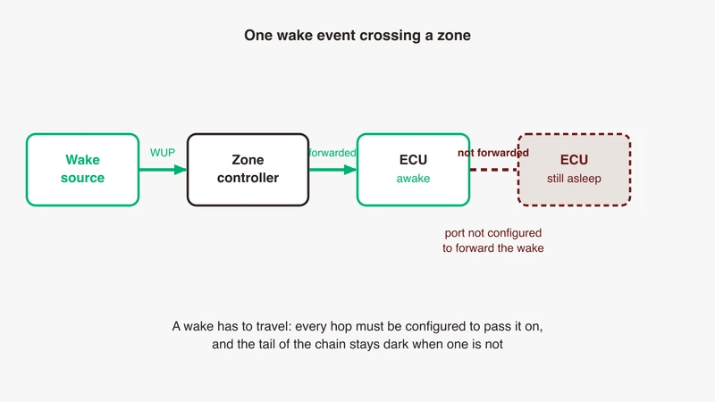
A wake reaching a switch does not continue by itself. The specification requires multi-PHY devices to implement a selective wakeup forwarding mechanism, and that when such a device detects a wake-up request on one port it must be possible to forward it to other PHYs. The 1000BASE-T1 revision adds that forwarding shall be possible to selectable target PHYs, with the wake sent over the medium as WUP or WUR depending on that port’s link status.
Both phrases are doing work. Selective means a configured mapping from source port to target ports. Must be possible means the silicon offers the capability rather than performing it unprompted. A port nobody mapped is a port where the wake stops, and the tail of the chain stays dark. The pin path is the other half: where several PHYs share a board, one PHY’s wake-forwarding output and another’s local-wake input are commonly tied together, which is why the 40 microsecond minimum pulse width is the contract between two PHYs on one PCB.
Selective wake against waking the whole network
Partial networking is the point of TC10, so a forwarding map that wakes everything is not a functional bug: every ECU comes up and the vehicle behaves. It is a current bug, and it never appears in a log. The evidence is on a current meter, comparing quiescent draw against the ECUs that were supposed to stay asleep and against the per-port targets above. Measure it before concluding that selective wake works. Where sleep and wake sits in a whole vehicle communication architecture decides which reading is the interesting one.
Why it fails in practice
Seven failure modes. Several look identical from software, which is why the list is worth keeping.
1. Mixed vintage. A TC10 node linked to a partner that does not implement TC10. The link comes up perfectly, because the specification says implementing the extensions will not impact interoperability with a basic 802.3bw PHY when the new commands are not used. Then the sleep handshake fails after REQ_timer because no LPS comes back, or the node sleeps by a local path and nothing wakes it because the partner has no WUP to send. A vendor’s own answer on a public support forum puts it in one line: devices that support TC10 can only wake up remote devices that support TC10 as well. Symptom: link fine, sleep fails at 16 ms, or sleeps and never wakes.
2. Basic sleep configured where TC10 was intended. Usually a strap, a register default, or a function-select field nobody set. Symptom: local sleep works and the current drops, but no remote wake and no wake forwarding. Identical to failure 1 from the far end.
3. Speed mismatch on the wake pattern. The 1000BASE-T1 specification says a WUP is only reliably detected if the responder supports and operates in the WUP’s associated speed mode, and its footnote is unambiguous: a WUP transmitted by a PHY operating in 100BASE-T1 mode is not guaranteed to be detected by a 1000BASE-T1 device or the reverse. Multi-speed PHYs must use the pattern for their configured speed. Symptom: wake works between two nodes of one speed, not across a speed boundary.
4. Wake source mismatch. The design assumes a link wake; the hardware only offers a local pin wake, or the pin exists but nothing drives it for 40 microseconds. Symptom: wake works when a person toggles something, never when the network should have.
5. INH sequencing slower than the budget. The wake is real and on time, and the node cannot answer because its rails are still ramping or its MCU is still booting. Symptom: intermittent, load and temperature dependent, and it moves when you change an unrelated regulator. Usually filed as a network fault and closed as a power fault.
6. Spurious wakes. Cable disconnect and reconnect, noise on a harness-routed wake line, or a partner that cycles. The specification pushes back with the 10 µs rejection threshold on the local wake pin, the optional 10 ms window for slow harness wake lines, and energy detection held disabled during SLEEP_SILENT to prevent a mutual wakeup through LPS commands. But it also requires that any transmitted idle pattern on the link trigger energy detection, so a partner that starts transmitting for any reason is a legitimate wake. Symptom: the battery, not the link.
7. Switch port not configured to forward. The wake arrives at the zone controller and stops, because no source-to-target mapping was written for that port. Symptom: the first hop wakes, the tail of the chain stays dark, and nothing in any log says why.
How to measure it
The interesting part of TC10 happens while the link is down, so a frame capture sees nothing: there are no frames. Capture method for the traffic either side of a sleep is covered in our capture guide, and a media converter in the bench path holds a T1 PHY with a role and sleep behaviour of its own, one of the selection questions in our media converter guide. For the event itself the instrument is an oscilloscope.
On the differential pair. WUP is directly observable; LPS is not, because it is encoded in the scrambler stream on 100BASE-T1 and in an OAM frame on 1000BASE-T1. What the scope gives you for the sleep handshake is the transition to silence and its timestamp, not the commands themselves. Look for a pulse of 1 ms plus or minus 0.3 ms, and on 1000BASE-T1 check the amplitude against the specification. Trigger on activity after a quiet period and you have the wake event with a timestamp.
On INH against the supply rail. Two channels, INH and the rail it gates, gives you the ramp directly, and budget failures become a picture rather than an argument. Extend that into intervals with owners: wake to INH, INH to rails good, rails to management-interface activity, then link-up. A published vendor timing measurement uses the same decomposition.
Current in each state. Active, sleep, and the transient during wake. The only measurement that proves selective wake is selective.
A capture cannot tell you whether the node was asleep by design or dead. Log link state and INH alongside anything else you record, or a correct sleep reads as a fault for the rest of the analysis.
TC10 in a test plan
TC8 and TC10 are separate committees with separate documents. The OPEN Alliance describes TC8 as responsible for automotive Ethernet ECU test and conformance specifications throughout all seven OSI layers; TC10 owns sleep and wake-up. The OPEN Alliance roadmap still lists the 100BASE-T1, 1000BASE-T1 and MultiGBASE-T1 sleep and wake-up test suites as pending, so TC10 behaviour is verified against the specification and the OEM requirement rather than against a released suite. A device can pass an interoperability and protocol suite and still fail to sleep or wake on the harness it ships on, so a real programme runs both. Our automotive Ethernet guide places each conformance term.
If you have multidrop segments, track the 10BASE-T1S side. TC14’s published scope lists collaboration with TC10 on the wakeup and sleep specification, and the OPEN Alliance now lists a 10BASE-T1S Sleep/Wake-up Specification. A public IEEE 802.3da contribution sets out a wake and sleep baseline for that physical layer, recognisable but not identical: the same forwarding structure and a TWU_Forwarding of 1 ms, but state names built around low power rather than sleep, a LOW_POWER_timer of 2 ms, a wake-up tone of 12 periods of a 625 kHz tone, and timing that distinguishes a quiet segment from a partial one because the medium is shared. Do not carry 100BASE-T1 timer values across.
Before a conformance house sees the unit, have four things ready: the PHY configuration actually loaded at run time rather than the one in the reference driver, the wake source design per link, scope captures of WUP and of INH against the rails, and a current measurement per state. Flashing and handling Ethernet ECUs on the line is a separate discipline, covered in our production programming article.
Where GSAS fits
TC10 work spans three disciplines that usually report to different people: the PHY configuration, the power sequencing, and the network management that decides who sleeps. Most of the failures above sit on a boundary between two of them, which is why they survive so long. Bring us the PHY configuration you actually load, the wake source design per link, and whatever scope captures you have, and we work the wake path through with your team.
Our applications engineers work with automotive teams across Bengaluru, Pune, Chennai and Hyderabad on bench setup and pre-conformance measurement: a scope on the pair and on INH, the wake-to-link time decomposed into intervals with owners, and quiescent current per state so selective wake is shown rather than assumed.
Our automotive Ethernet capability page sets out how we work with engineering teams, and you can request a consultation describing your topology, the wake sources and the wake-to-ready number you have been given.
References
- OPEN Alliance, OPEN Sleep/Wake-up Specification for Automotive Ethernet, version 2.0, 21 February 2017, public release: https://opensig.org/wp-content/uploads/2024/01/TC10-Wake-up-and-Sleep-Specification-for-Automotive-Ethernet_11-2017.pdf
- OPEN Alliance, 802.3bp Sleep/Wake-up Specification for Automotive Gigabit Ethernet, version 1.0, 27 October 2021, public release: https://opensig.org/wp-content/uploads/2024/01/TC10_1000BASE-T1_sleepwakeup_spec_1.0.pdf
- OPEN Alliance, TC10 committee page: https://opensig.org/tech-committee/tc10-automotive-ethernet-sleep-wake-up/
- OPEN Alliance, TC8 committee page: https://opensig.org/tech-committee/tc8-automotive-ethernet-ecu-test-specification/
- OPEN Alliance, TC14 committee page: https://opensig.org/tech-committee/tc14-interoperability-compliance-tests-for-10base-t1s-phys/
- IEEE 802.3da public contribution, EEE Wake/Sleep baseline preview, July 2023: https://www.ieee802.org/3/da/public/0723/802.3da%20EEE%20WakeSleep%20Baseline%20Preview_a.pdf
- Silicon vendor application note, system implementation of OPEN Alliance TC10 sleep and wake-up, October 2022. Corroboration only: https://www.ti.com/lit/pdf/snla411
- Silicon vendor application note, TC10 system timing measurements, January 2023. Source of the wake-to-link decomposition: https://www.ti.com/lit/pdf/snla417
- Public thread on a silicon vendor’s support forum, remote wake over a single-pair link: https://e2e.ti.com/support/interface-group/interface/f/interface-forum/1427678/dp83tc813r-q1-tc10-wakeup-from-lan
- Public thread on a silicon vendor’s community forum, basic sleep against TC10 sleep, February 2024, unresolved: https://community.nxp.com/t5/Other-NXP-Products/Tja1103-ETH-PHY-basic-sleep-functionality/td-p/1817618
Also appears in:
Building for Automotive & Mobility?
Talk to our application engineers for personalized tool recommendations.