In short
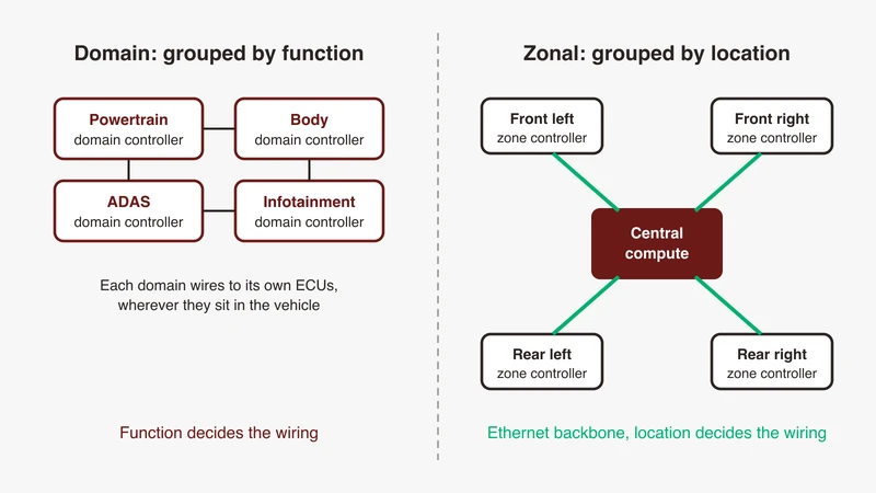
A domain architecture groups ECUs by function such as powertrain or infotainment, while a zonal architecture groups them by physical location in the vehicle and connects each zone to central compute over an Ethernet backbone. Domain grouping follows the function tree; zonal grouping follows the harness. The consequence is that in a zonal design local input and output stay at the zone, application software moves to central compute, and the network stops being a set of function buses and becomes the architecture itself.
Most writing about zonal architecture describes a destination rather than a change. This is the other read: what physically moves, what the network has to become to carry it, and what it does to diagnostics, rest bus simulation and time synchronisation on your bench.
One discipline runs through it. The harness mass, harness length, cost-saving and ECU-count figures repeated in almost every article on this subject are, as far as we could establish, not traceable to a public document that states them with a method. So this article gives the direction of each effect, names the public source for it, and where a number is not citable says so instead of repeating it. That includes the India section, which carries no statistics. For SDV framing, see the software-defined vehicle piece.
Three architectures in one page
Distributed: one ECU per function
Still most of what is on Indian roads. A function gets a box, the box sits near the thing it controls, and it talks to peers over a control bus. Its virtue is independence: the box is testable alone and a fault has an obvious address. Its cost is that wiring, connectors and bus load all scale with function count.
Domain: grouped by function
The consolidation step. Functions are grouped into domains, typically powertrain, body, chassis, infotainment and ADAS, each with a controller that hosts that domain’s applications and owns the buses beneath it.
Application software moves up, so the boxes below get simpler, and the domain controller becomes a gateway because traffic between domains crosses a boundary. Grouping is still by function, so a domain’s devices sit anywhere in the vehicle and the harness still reaches every one of them.
Zonal: grouped by physical location, plus central compute
The domain vs zonal difference comes down to one thing: zonal changes the grouping principle. Controllers are placed by location: front-left, front-right, rear, sometimes roof or centre. Each terminates whatever sensors, actuators, switches and short buses sit near it, regardless of function, and connects to central compute over a backbone.
The consequence people miss is the one that matters. A controller that no longer owns a function cannot host that function’s application software, because the function’s other devices terminate at other zones. So applications move to central compute and the zone becomes an input, output and power node on a network. Everything else follows from that.
The comparison, row by row
| Distributed | Domain | Zonal | |
|---|---|---|---|
| Grouping principle | One ECU per function | By function: powertrain, body, chassis, infotainment, ADAS | By location |
| Wiring | Every ECU to every peer | Domain controller to its devices wherever they sit | Short local runs to the nearest zone, plus a backbone |
| Compute location | In the box | In the domain controller | In central compute, not the zone |
| Network | Control buses, function by function | Control buses below, Ethernet between domain controllers | Ethernet backbone, control buses and multidrop in-zone |
| Update model | Per ECU, at service | Per domain controller | Central, zone reached through it |
| Diagnostic path | Often on the target’s bus | Through a gateway to a domain bus | Over IP to central compute, then the zone |
Read the compute row and the diagnostic row together: that is where a validation plan written for a domain programme stops working.
What actually moves in a zonal design
Compute centralises, input and output stay local
A wheel speed sensor is still read close to the wheel and its conditioning still sits near the connector. What changes is where the code that uses the reading runs.
So a zone controller is not a smaller domain controller. It is closer to a powered, protocol-converting endpoint that happens to have a microcontroller in it. Some real-time control stays local, because a loop cannot afford a round trip per iteration, and deciding what stays is one of the genuinely hard calls in a zonal programme. It also decides what your bench has to simulate.
Power distribution follows the data, and why that matters to the harness
This is usually described in slogans, so here is what the standards say. IEEE 802.3 has repeatedly written optional power delivery into automotive single-pair projects: the approved P802.3cg objectives include one or more optional power distribution techniques for 10 Mbit/s single-pair PHYs, and the approved P802.3ch objectives include optional Clause 104 power over data lines. Outside 802.3 the same idea is written down again. IEEE Std 2977-2021 is the IEEE adoption of the MIPI Alliance A-PHY specification, a SerDes link rather than Ethernet, and the P802.3dm PAR quotes its scope while listing it as a partially overlapping standard: an asymmetric data link in a point-to-point or daisy-chain topology that “reduces wiring, cost and weight, as high-speed data, control data and optional power share the same physical wiring”.
That is the citable direction. It is not a number, and the standards bodies do not offer one.
One limit is worth knowing before you draw a zone diagram. The P802.3cg tutorial states that the 15 m point-to-point 10BASE-T1S link is compatible with Clause 104 PoDL powering, while for half duplex multidrop, 8 nodes over 25 m, multidrop power is not defined in 802.3cg. That gap was closed after 802.3cg. IEEE Std 802.3da-2026, approved 12 February 2026, carries an approved objective to specify optional plug-and-play power distribution over the mixing segment, with detection before full power is applied and bounded interruption when a node is added or removed. So multidrop power exists, but it is a separate amendment from the one that defined the PHY, and which of the two your silicon implements is a question to ask your supplier.
Software decouples from the box it runs on
The decoupling idea predates zonal architecture. The AUTOSAR Classic Platform describes the virtual functional bus as decoupling applications from the infrastructure, communicating via dedicated ports and handling communication both within the individual ECU and between ECUs, so that from an application point of view no detailed knowledge of lower-level technologies or dependencies is needed.
The Adaptive Platform adds a different runtime shape: AUTOSAR describes it as implementing the AUTOSAR Runtime for Adaptive Applications, with functional clusters grouped into services and an Adaptive Platform Basis on a POSIX OS and a (virtual) machine, where services may be distributed in the in-car network. Unlike Classic, AUTOSAR says, the Adaptive runtime environment dynamically links services and clients during runtime.
Note what AUTOSAR does not say: that Classic belongs in zones and Adaptive in central compute. That mapping is a programme decision, not a statement in the standard.
The network is the architecture
An Ethernet backbone between zones
The backbone carries traffic from every function at once, so it needs capacity that scales with the switch rather than the medium, across a range from control-message trickle to sensor aggregation. That is what the automotive T1 physical layers give: one balanced pair per link, specified in IEEE 802.3 from 10 Mbit/s to 25 Gbit/s, with reach shortening as the rate climbs.
The T1 family comparison puts every variant in one table with rate, reach, cabling and the master and slave question; the complete automotive Ethernet guide covers the stack above the pair; Ethernet in the vehicle communication architecture is the topology view.
Inside a zone: control buses and multidrop
Zonal does not delete CAN, it relocates it. A CAN or CAN FD segment inside a zone is short, has few nodes, and terminates at the zone controller instead of running the length of the vehicle.
Ethernet has one option shaped like that. IEEE 802.3cg defines an optional half duplex multidrop mode for 10BASE-T1S, with an approved objective of a mixing segment supporting at least 8 nodes for up to at least 25 m. The task force tutorial is candid about the limits: capacitance limits node count, gauge limits reach, repeaters are not specified. Those are the 802.3cg limits. IEEE Std 802.3da-2026, approved 12 February 2026, was chartered to push the mixing segment to at least 16 nodes over at least 50 m and to add optional PLCA node ID allocation, so check which amendment a candidate PHY implements before you size a segment. It is a genuine shared medium competing with a bus you already know, and automotive Ethernet versus CAN sets that trade out.
Where TSN stops being optional
Once the backbone carries control traffic, camera traffic and diagnostics on the same links, queueing inside the switches becomes the latency story. The IEEE 802.1 TSN task group states its charter as deterministic connectivity through IEEE 802 networks, “guaranteed packet transport with bounded latency, low packet delay variation, and low packet loss”.
The mechanisms are separately named standards, worth telling apart when a requirement lands on your desk:
- IEEE Std 802.1AS-2025, Timing and Synchronization for Time-Sensitive Applications
- IEEE Std 802.1Qav-2009, Forwarding and Queueing Enhancements for Time-Sensitive Streams, the credit based shaper
- IEEE Std 802.1Qbv-2015, Enhancements for Scheduled Traffic
- IEEE Std 802.1Qbu-2016, Frame Preemption
- IEEE Std 802.1Qci-2017, Per-Stream Filtering and Policing
- IEEE Std 802.1CB-2017, Frame Replication and Elimination for Reliability
- IEEE Std 802.1DG-2025, Time-Sensitive Networking Profile for Automotive In-Vehicle Ethernet Communications
None of it is automatic. The bound exists once the shapers, schedules and synchronisation are configured correctly, which makes it a property of your configuration and something your bench has to verify.
Service oriented communication replaces static signal routing
In a signal-routed vehicle a frame goes somewhere because a database says it does. In a service oriented vehicle a client asks and a provider answers.
The public AUTOSAR Foundation specification for SOME/IP describes it as service oriented communication over a network, based on service definitions listing what the service provides, where a service can consist of combinations of zero or multiple events, methods and fields. Events send data cyclically or on change from provider to subscriber, methods let a subscriber issue remote procedure calls executed on the provider side, and fields combine one or more of a notifier, a getter and a setter. Serialization is how that data is represented in PDUs carried as UDP or TCP payload over an IP-based in-vehicle network.
Two consequences for debugging. What is on the wire depends on who has subscribed, so a quiet link is not necessarily broken. And message identity is a service and method rather than a frame ID, which changes how you filter a capture. SOME/IP explained covers the format and service discovery; if frames arrive but nothing decodes, the decoding fix list works through the causes.
Segmentation as a safety and security boundary
A single flat backbone carrying every function has to be argued for, not assumed. The IEEE 802.1 Working Group that publishes the bridging and VLAN standard 802.1Q also publishes 802.1AE MAC Security, 802.1X port-based network access control and 802.1AR secure device identity, alongside the TSN mechanisms above. Segmentation, stream policing and device identity come from one standards family and interact: a per-stream filtering rule is a safety and a security mechanism at once.
The numbers people quote, and what is actually citable
Harness length, mass and cost
The honest position. We looked for a public document stating the repeated harness mass saving, harness length reduction, cost-per-vehicle saving or ECU-count reduction, with a method behind it. We did not find one.
The nearest thing to a citable direction is narrower than the claim it is usually used to support. IEEE Std 2977-2021, the IEEE adoption of MIPI A-PHY, states in its scope that sharing high-speed data, control data and optional power on one cable reduces wiring, cost and weight. That is a statement about one sensor link, not about a vehicle harness, and not about domain versus zonal grouping at all. For the zonal harness claim specifically we found no public document with a method behind it, so this article states no direction for it either.
If someone hands you a business case built on a number, ask which vehicle, which harness, which baseline and which cost book. If the answer is a slide, you have a slide, not a number. The rule this article follows: no figure ships without a public link, and where none exists the direction ships and the figure does not.
Sensor bandwidth growth
The trend is real and documented, in the form of what standards bodies decided to work on. The IEEE P802.3dm PAR states the need directly: automotive in-vehicle networks are transitioning to Ethernet, and high-bandwidth links such as imaging sensors at end-nodes where the backchannel is low bandwidth are important parts of that transition, with those end-nodes highly constrained on complexity and power consumption. The approved objectives put a shape on it: point-to-point PHYs carrying up to 10 Gbit/s one way and up to 100 Mbit/s the other, over balanced-pair and unbalanced coaxial link segments of at least 15 m with up to four inline connectors. An entire task force exists because camera links are asymmetric, better evidence than any market forecast.
Consequences for software
Platform choice is a decision, not a rule
Take the two AUTOSAR descriptions at face value and the decision looks like this. A zone controller doing deterministic input and output on a microcontroller matches the Classic layering of application, RTE and basic software. A central compute node hosting several independently updated applications on a POSIX machine matches Adaptive. Many programmes run both, and the Foundation standard exists to enforce interoperability between them, carrying the shared specifications, SOME/IP among them. Do not let the architecture diagram decide the platform.
Update paths and rollback
Centralised compute makes update tractable, because there is a node to talk to and a place to stage from. It also concentrates the failure mode, because the zone is reached through that node. The question a zonal design forces is not “can we do OTA” but “what is the state of the vehicle if the update reaches central compute and not one zone”, and whether the rollback path uses the route that just failed. That is a system property to design and test, and the regulatory frame around vehicle cybersecurity and software update management is UNECE R155 and R156, covered in our compliance overview. For the path out to a backend, the telematics unit deep dive covers that side.
Diagnostics move behind a gateway
In a distributed vehicle the tester was often on the target’s bus. In a zonal vehicle it is not, and the session is carried over IP: UDS services defined in ISO 14229 tunnelled over DoIP as defined in ISO 13400, which IANA registers on port 13400, doip-data over TCP and doip-disc over UDP.
Two things change for whoever holds the tester. Routing and addressing are part of the diagnostic path and can fail independently of the ECU you wanted. And a negative response or a timeout may come from a gateway rather than the target, so the first question is which hop answered. UDS explained, DoIP explained and how OBD2, DoIP and UDS relate cover the three layers in order.
Keys and credentials become a manufacturing problem
Nodes that authenticate to each other have to hold credentials before they leave the line, which turns a security design into a production process with its own equipment, logging and traceability. Key injection in production covers it.
Consequences for test and validation
Rest bus simulation now spans two protocol families
A zone controller sits between local devices and a backbone, so its rest bus has to be both: the CAN, LIN or multidrop devices below it and the service traffic above it, in the same run, with consistent state between the two. A rest bus that speaks one side leaves the unit under test in a condition it will never see in a vehicle. This is the biggest bench change a domain-to-zonal transition produces, and it is usually found late.
Capturing a zone
Visibility moves. Traffic once observable on a vehicle-length bus now terminates a metre from the device that produced it, and only aggregated or transformed data crosses the backbone. A backbone capture tells you what central compute saw, not what the sensor sent.
Getting inside the zone means a tap or a mirror. Point-to-point T1 links are not a shared medium you can passively listen to the way a control bus was, and a mirror shows what the switch decided to forward, at the switch’s timing rather than the wire’s. For the signal on the pair rather than the frames, scoping automotive Ethernet alongside CAN FD, LIN and FlexRay covers that side of the bench.
Time sync becomes a test object, not an assumption
Correlating a CAN event with an Ethernet event needs a shared timebase, and the two sides do not offer one symmetrically. On the Ethernet side synchronisation is standardised, IEEE Std 802.1AS-2025 with an automotive profile in IEEE Std 802.1DG-2025. On the control bus side there is no equivalent at the data link layer, but there is one above it: AUTOSAR publishes Time Synchronization over CAN, Classic Platform document 674, which distributes a global time across a CAN network. So a CAN capture may carry two clocks, the vehicle’s global time domain if the network runs one, and the timestamp your capture hardware applied if it does not. Decide early which is authoritative, and confirm which one you actually have.
And if a function’s correctness depends on synchronisation, synchronisation is in scope for validation rather than infrastructure you assume: test what happens when a grandmaster changes, when a link is slow to come up, and when sync degrades rather than fails. The standards give the mechanism, the evidence is yours to produce.
What a HIL rig has to grow
Adding it up: two protocol families simulated together, capture inside the zone as well as on the backbone, one timebase across both, diagnostics over IP, and TSN configuration verified rather than assumed. A domain-era rig usually covers the first and part of the fourth. Scoping that gap at the start is cheaper than finding it during integration, and domain and zone controller work in practice is a reference point for the bring-up and production side.
Adoption reality for India programmes
Qualitatively, and with no statistics because we found no Indian public source stating any: teams we talk to here are rarely asked to design a clean-sheet zonal vehicle. They are asked to build a zone controller or a central compute node for a platform defined elsewhere, to validate one against a specification written elsewhere, or to add zonal characteristics to part of a domain-era platform. Mixed architectures, harder to test than either pure form because the assumptions differ across the vehicle.
Commercial constraints shape the engineering more than the architecture diagrams admit. Volume, cost target and sourcing decide whether a function gets a microcontroller in a zone or a slice of central compute, and for many segments of the Indian market the answer is not the one the think-pieces assume. A two-wheeler programme and a premium passenger vehicle programme do not arrive at the same architecture, and neither is wrong.
The gap that shows up most is not architectural knowledge, it is debugging range. A zone controller fault at 2am spans a control bus, a switched Ethernet link, a service call, a synchronisation domain and a diagnostic path, and the person on the bench has to be credible on all five. Teams with deep CAN experience and shallow switched-network experience lose the night on the network side.
Where GSAS fits
GSAS Micro Systems is an engineering partner, and our role here is narrow: we do not design your E/E architecture. What we do is work through, at the architecture stage, what the choice does to your test and validation plan, the part usually costed last and found late.
The questions are the ones above. Which functions stay local and which move, because that decides what a rest bus has to present. Where you need visibility inside a zone rather than on the backbone. Whether TSN configuration is yours to prove or a supplier’s. Whether your bench can hold one timebase across two protocol families. Answering those honestly usually changes the equipment conversation, sometimes by removing things from it.
Our engineers work in IST, so a session lands inside your working day, and quotations are issued in INR through the procurement channels Indian OEMs and tier-one suppliers already use. The teams we work with sit in Bengaluru, Pune, Chennai and Hyderabad. Start with the automotive Ethernet capabilities page, and request a scoped conversation to walk through a specific architecture. Where the answer is that you do not need to buy anything yet, that is the answer you get.
References
- IEEE 802.1 Time-Sensitive Networking task group (TSN charter of guaranteed packet transport with bounded latency, low packet delay variation and low packet loss; standard titles for 802.1AS-2025, 802.1Qav-2009, 802.1Qbv-2015, 802.1Qbu-2016, 802.1Qci-2017, 802.1CB-2017 and 802.1DG-2025): https://1.ieee802.org/tsn/
- IEEE 802.1 Working Group (charter across 802 LAN/MAN architecture, internetworking, 802 security and network management; 802.1Q bridging maintenance; 802.1AE MACsec, 802.1X and 802.1AR in the Security task group): https://1.ieee802.org/
- IEEE P802.3cg 10 Mb/s Single Twisted Pair Ethernet Task Force objectives, approved 8 March 2018 (link segment up to 4 inline connectors for at least 15 m; mixing segment supporting at least 8 nodes for at least 25 m; optional half duplex multidrop; one or more optional power distribution techniques): https://www.ieee802.org/3/cg/objectives_3cg_0318.pdf
- IEEE P802.3cg task force tutorial, “10Mb/s Single Pair Ethernet: A guide”, January 2019 (15 m point-to-point compatible with Clause 104 PoDL powering; multidrop power not defined in 802.3cg; capacitance limits node count, gauge limits reach, repeaters not specified): https://www.ieee802.org/3/cg/public/Jan2019/Tutorial_cg_0119_final.pdf
- IEEE P802.3da 10 Mb/s Single Pair Multidrop Segments Enhancement Task Force, IEEE Std 802.3da-2026 approved by the IEEE-SA Standards Board on 12 February 2026, approved objectives (mixing segment supporting up to at least 16 nodes for up to at least 50 m; optional PLCA node ID allocation method; backward compatibility with Clause 147 PHYs; optional plug-and-play power distribution over the mixing segment; detection of at least one MPD before applying full operating power; addition or removal of nodes on a powered mixing segment with a bounded interruption): https://www.ieee802.org/3/da/802d3da_objectives.pdf
- IEEE P802.3cy Greater than 10 Gb/s Electrical Automotive Ethernet Task Force, updated approved objectives, 14 July 2022 (a 25 Gb/s data rate at the MAC/PLS service interface over an automotive link segment): https://www.ieee802.org/3/cy/P802d3cy_OBJ_UPDATED_APPROVED_07_14_22.pdf
- IEEE P802.3ch Multi-Gig Automotive Ethernet PHY objectives, approved 16 March 2017 (2.5, 5 and 10 Gbit/s over an automotive link segment with up to four inline connectors for at least 15 m; optional Clause 104 power over data lines on appropriate media): https://www.ieee802.org/3/ch/0317_approved_objectives_3NGAUTO.pdf
- IEEE P802.3dm Project Authorization Request, approved 21 March 2024 (need for the project: in-vehicle networks transitioning to Ethernet, high-bandwidth imaging sensors at end-nodes with a low-bandwidth backchannel, end-nodes highly constrained on complexity and power; in the overlapping-standards section, the quoted scope of IEEE Std 2977-2021, the IEEE Standard for Adoption of MIPI Alliance Specification for A-PHY Interface (A-PHY) Version 1.0, an asymmetric data link in a point-to-point or daisy-chain topology that reduces wiring, cost and weight because high-speed data, control data and optional power share the same physical wiring): https://www.ieee802.org/3/dm/P802.3dm_PAR.pdf
- IEEE P802.3dm approved objectives, March 2026 (up to 10 Gbit/s in one direction and up to 100 Mbit/s in the other, over balanced-pair and unbalanced coaxial link segments of at least 15 m with up to four inline connectors): https://www.ieee802.org/3/dm/public/0326/Objectives_ISAAC_01_0326.pdf
- AUTOSAR Classic Platform (three software layers running on a microcontroller: application, RTE and BSW; the virtual functional bus decoupling applications from the infrastructure and handling communication within and between ECUs): https://www.autosar.org/standards/classic-platform
- AUTOSAR Adaptive Platform (AUTOSAR Runtime for Adaptive Applications; functional clusters grouped into services and the Adaptive Platform Basis; POSIX OS and (virtual) machine; the Adaptive runtime environment dynamically links services and clients during runtime): https://www.autosar.org/standards/adaptive-platform
- AUTOSAR Foundation (purpose is to enforce interoperability between the AUTOSAR platforms; contains common requirements and technical specifications, for example protocols, shared between the platforms): https://www.autosar.org/standards/foundation
- AUTOSAR Foundation R24-11, SOME/IP Protocol Specification, document 696 (service oriented communication over a network; events, methods and fields; serialization into PDUs carried as UDP or TCP payload over an IP-based automotive in-vehicle network): https://www.autosar.org/fileadmin/standards/R24-11/FO/AUTOSAR_FO_PRS_SOMEIPProtocol.pdf
- AUTOSAR Classic Platform R24-11, Specification of Time Synchronization over CAN, document 674 (the CanTSyn module handles the distribution of time information over CAN buses): https://www.autosar.org/fileadmin/standards/R24-11/CP/AUTOSAR_CP_SWS_TimeSyncOverCAN.pdf
- IANA Service Name and Transport Protocol Port Number Registry (doip-data on TCP 13400 and doip-disc on UDP 13400): https://www.iana.org/assignments/service-names-port-numbers/service-names-port-numbers.xhtml
- ISO catalogue listings for ISO 14229 (Road vehicles, Unified diagnostic services) and ISO 13400 (Road vehicles, Diagnostic communication over Internet Protocol) for part titles and published scopes: https://www.iso.org/
Also appears in:
Building for Automotive & Mobility?
Talk to our application engineers for personalized tool recommendations.