In short
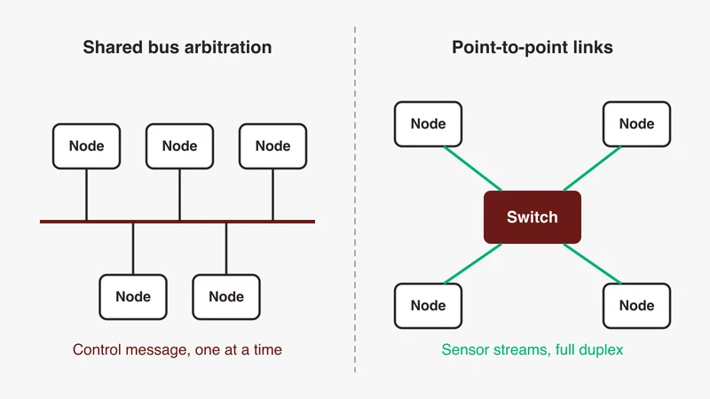
CAN and automotive Ethernet solve different problems and coexist in the same vehicle. CAN and CAN FD carry short, prioritised control messages on a shared two-wire multidrop bus, with arbitration limited to 1 Mbit/s and a data field of up to 8 bytes on CAN CC or up to 64 bytes on CAN FD. 100BASE-T1 carries 100 Mbit/s full duplex point to point over a single balanced pair for cameras, driver assistance, infotainment and diagnostics. Choose per function, then join the two with a gateway.
Every few months a project team in Bengaluru or Pune arrives at the same meeting. The new platform has cameras, a driver assistance stack and over-the-air updates, someone has written “Ethernet” on the architecture slide, and the question in the room is whether the CAN benches, the CAN expertise and the CAN harness are about to become legacy.
They are not. The comparison that usually gets written, the one ending in “Ethernet is the future”, is the wrong shape. CAN and automotive Ethernet answer different questions, and a vehicle that carries Ethernet generally carries CAN too. What follows is that comparison as a decision table: the figures on both sides with their public sources, then what changes on your bench.
Every CAN figure here comes from the public CAN in Automation knowledge base, the IEEE task force objectives sheets are the source for the T1 rate, reach and connector figures, the Ethernet frame size is from RFC 894, and every determinism claim about switched networks is from the IEEE 802.1 TSN pages. All are listed in the References.
The short answer: they coexist, they do not compete
One sentence for a design review
CAN and CAN FD carry short, prioritised control messages on a shared two-wire multidrop bus, while 100BASE-T1 Ethernet carries 100 Mbit/s full duplex point to point for cameras, driver assistance, infotainment and diagnostics. Pick per function, then join the two with a gateway.
The mental model: control traffic versus data traffic
The split that holds up in practice is not old versus new, it is control versus data.
Control traffic is a wheel speed, a torque request, a door lock state. It is a handful of bytes, it repeats at a fixed period, and its value comes from arriving on time rather than from arriving large. CAN was built around that shape: CiA describes the CAN CC data field as varying between zero and up to eight data bytes, and describes the identifier as indicating the content and defining the network access priority, so that in overload conditions transmission requests are handled in the order of their importance for the system as a whole.
Data traffic is a camera frame, a radar point cloud, a logging stream, a software image. It is large, it is bursty, and its value comes from throughput. No bit rate increase on a shared two-wire bus with an 8 or 64 byte data field turns it into a good carrier for that.
Once a platform has both kinds of traffic, it has both kinds of network. For the wider map of what sits on the Ethernet side, the companion guide on what automotive Ethernet is covers the T1 physical layer family and the stack above it.
Bandwidth, framing and latency compared
CAN and CAN FD: arbitration, 8 and 64 byte payloads, data-phase rate
CAN CC, the classic protocol, has its data link layer standardised in ISO 11898-1 and the CAN high-speed physical medium attachment sub-layer in ISO 11898-2. CiA states that for CAN high-speed transceivers “the maximum bit-rate is 1 Mbit/s”, and that because of the arbitration method the maximum possible bit rate depends on network length, with 40 m theoretically reachable at 1 Mbit/s before real cables, connectors and sample point settings shorten it. The frame carries an 11-bit identifier in the base frame format or a 29-bit identifier in the extended frame format, and a data field of zero to eight bytes.
CAN FD changes two things. CiA describes it as overcoming two CAN CC limits: you can transmit data faster than 1 Mbit/s, and the payload is up to 64 byte long rather than limited to 8 byte. The rate change is conditional, and this is the part that comparison articles routinely get wrong. In CiA’s own words, “in the arbitration phase the bit rate depends on the network topology and is limited to 1 Mbit/s; in the data phase the bit rate is limited by the transceiver characteristics”. So a CAN FD frame is a slow header wrapped around a fast data field.
What the data phase reaches depends on the transceiver, and CiA is specific. CAN FD transceivers with tighter symmetry features are described as suitable for bit rates higher than 1 Mbit/s and usable in networks with data-phase bit rates of 2 Mbit/s and more. CAN SIC transceivers, standardised in ISO 11898-2:2024, are listed with the data-phase speed limited to 5 Mbit/s. CiA also notes that CAN SIC or CAN SIC XL transceivers may limit the arbitration phase speed to 667 kbit/s when all CAN identifier values are applied. A headline “CAN FD speed” number quoted without saying which phase it applies to and which transceiver class it assumes is unusable.
100BASE-T1: 100 Mbit/s full duplex over one pair
The IEEE P802.3bw task force objectives are short and public, and they settle the Ethernet side of the table. They call for 100 Mb/s operation in automotive environments over a single balanced twisted pair, support for a speed of 100 Mbit/s at the MAC and PLS service interface, full duplex operation only, a bit error ratio of 1e-10 or better, and a link segment supporting point to point operation over single twisted pair with up to four inline connectors using balanced cabling for at least 15 m reach.
Two of those objectives matter here more than the rate does. “Full duplex operation only” means the 100 Mbit/s figure applies in each direction at once, which has no equivalent on a shared CAN bus. And the objectives to “preserve the IEEE 802.3/Ethernet frame format at the MAC client service interface” and “preserve minimum and maximum frame size of the current IEEE 802.3 standard” mean the payload is the ordinary Ethernet one, a maximum data field of 1500 octets, the figure RFC 894 records for classic Ethernet and which 802.3bw preserves unchanged. For anything that has to be split across frames, per-frame overhead falls away on the Ethernet side.
100BASE-T1 is one member of a family rather than the whole of it. The complete guide sets out the five T1 rates and which one you meet where, and the T1 family explained compares every variant in one table.
Determinism: bit-wise arbitration versus switch queues and TSN shaping
This is where numbers are easiest to invent, so this section has none.
CAN resolves contention before the frame goes out. CiA describes bit-wise arbitration: when several frames compete for access at the same time, nodes compare identifiers bit by bit at the sample point under a wired-and mechanism, dominant overwrites recessive, and every node that transmitted recessive and observed dominant loses and becomes a receiver. Nothing is discarded and nothing collides. CiA’s conclusion is that since access is prioritised on the basis of the identifier, it is possible to guarantee low individual latency times in real-time systems. The cost is that the guarantee applies to the highest priority traffic; a low priority frame waits behind everything above it.
Switched Ethernet has no contention on the wire, because each link is point to point and full duplex. Contention moves inside the switch, where frames from several ingress ports queue for one egress port. Priority tags choose the order in that queue, but a frame already in transmission is not preempted by default, and an oversubscribed queue grows.
That gap is what the IEEE 802.1 Time-Sensitive Networking work exists to close. The IEEE 802.1 TSN page describes TSN as a set of standards specified by IEEE 802 with the charter “to provide deterministic connectivity through IEEE 802 networks, i.e., guaranteed packet transport with bounded latency, low packet delay variation, and low packet loss”. The mechanisms are individually named there: 802.1AS for timing and synchronisation, 802.1Qav credit-based shaper, 802.1Qbv scheduled traffic, 802.1Qbu frame preemption, 802.1Qci per-stream filtering and policing, 802.1CB frame replication and elimination, and 802.1DG-2025 as the automotive profile.
The practical difference for a design review: CAN’s timing behaviour is a property of the protocol and your identifier allocation. Ethernet’s timing behaviour is a property of your switch configuration. One is decided at network design time in a spreadsheet of identifiers, the other in shaper and schedule configuration that has to be verified on the bench.
The comparison table
| CAN CC | CAN FD | CAN XL | 10BASE-T1S | 100BASE-T1 | |
|---|---|---|---|---|---|
| Rate | Up to 1 Mbit/s (CAN HS PMA) | Arbitration limited to 1 Mbit/s; data phase limited by transceiver, 2 Mbit/s and more, 5 Mbit/s with CAN SIC | Nominal plus XL data phase; PWM coding allows 20 Mbit/s and higher depending on network design | 10 Mbit/s | 100 Mbit/s at MAC/PLS service interface |
| Data field | 0 to 8 bytes | Up to 64 bytes | 1 to 2048 bytes | Ethernet frame sizes | Ethernet frame sizes, 1500 octet maximum data field |
| Duplex | Half, shared medium | Half, shared medium | Half, shared medium | Half duplex, full duplex optional on a point to point segment | Full duplex only |
| Topology | Multidrop line, terminated at both ends with 120-Ohm resistors | Multidrop line | Multidrop line | Mixing segment, at least 8 nodes over at least 25 m | Point to point, up to four inline connectors, at least 15 m |
| Access | Bit-wise arbitration on the identifier | Bit-wise arbitration on the identifier | Bit-wise arbitration on the 11-bit priority ID; 32-bit acceptance field for filtering | CSMA/CD, optional PLCA | No contention on the link; queueing and shaping in the switch |
| Standard | ISO 11898-1, ISO 11898-2 | ISO 11898-1:2024 | ISO 11898-1:2024 | IEEE 802.3cg | IEEE 802.3bw |
Cost and the physical layer
Cost per node: what you are actually buying
Public sources will not give you a rupee figure, and neither will this article. Per-node and per-vehicle cost numbers for specific programmes are OEM internal figures, and quoting one you cannot source is worse than leaving the row blank.
What is public is the shape of the bill of materials. A CAN node is a protocol controller, typically already inside the microcontroller, plus a transceiver, plus a stub onto a pair that is already there; CiA notes that the automotive industry increasingly uses system basis chips that fold the transceiver in with regulators, watchdogs and wake-up logic. An Ethernet node is a MAC, again often on-chip, plus a T1 PHY, plus its own dedicated pair running back to a port. That third component has no CAN equivalent, and it is the one that scales.
Harness reality: pairs, shielding and connectors
The harness argument is structural rather than numerical. One CAN pair can serve many nodes; the CiA guidance is a line topology terminated at both ends with 120-Ohm resistors, with each node stubbed off it. One 100BASE-T1 link serves exactly two ports, so N nodes need N pairs back to a switch.
Against that, the Ethernet pair is a single balanced twisted pair rather than the four pairs of office cabling, at 1 Gbit/s the IEEE 802.3bp Type A automotive link segment is specified on unshielded balanced copper, and the 802.3bw link segment definition bounds the connector count at four inline connectors. Shielding stops being optional as the rate climbs, which is one more reason not to specify a faster T1 rate than a link needs.
Connector selection is a real cost line and a real EMC risk, but the families in use are supplier-specific and their qualification data is not public, so this article names none.
Where a switch adds cost that CAN never had
Adding the ninth node to a CAN segment costs a transceiver and a stub. Adding the ninth node to a switch with eight ports costs a new switch, or a second switch and an uplink, and every extra hop adds queueing that your timing analysis has to account for. That consequence is why zonal topologies exist: they cut the number of long Ethernet runs by aggregating short local buses into a controller with one Ethernet port facing the backbone.
This short video is a good statement of the popular framing, including the loose CAN FD rate figure the bandwidth section above corrects:
https://www.youtube.com/watch?v=hUvRAznEzqU&t=333
Topology consequences
CAN multidrop versus Ethernet point to point plus a switch
CiA describes CAN’s multi-drop capability as allowing distributed and redundant communication systems, and notes that it is easy to add CAN nodes to an existing network without hardware or software modifications to the present nodes, as long as the new nodes are receivers only. That property has no Ethernet equivalent. A new Ethernet listener needs a port, and a port needs a switch that has one free.
10BASE-T1S as the multidrop middle ground
IEEE 802.3cg is the one T1 family member that keeps the shared medium. Its objectives define a mixing segment on a single balanced pair supporting at least 8 nodes over at least 25 m, alongside a point to point link segment for at least 15 m. Access on that shared medium can be arbitrated by PLCA, PHY-level collision avoidance, an optional reconciliation sublayer that layers on top of CSMA/CD to give multidrop 10BASE-T1S bounded access latency. PLCA can be enabled or disabled through the management interface, so confirm it is on before assuming deterministic access.
For sensor and actuator segments that want Ethernet framing without a port per node, that is the middle ground.
What happens to your topology when one node moves
On CAN, relocating an ECU means re-routing a stub and re-checking stub length, termination and the speed-versus-length budget. On Ethernet it means re-routing a dedicated pair to a switch port, and if the nearest switch has no free port, a topology change. Plan the port budget the way you plan a CAN identifier allocation, with headroom.
Failure modes and how you debug them
What breaks on CAN
Termination first: a line not terminated at both ends with 120-Ohm resistors rings, and the symptom is intermittent form and CRC errors rather than a dead bus. Then the speed-versus-length budget, since CiA ties the achievable bit rate to network length and to the sample point setting. Then node-level faults: CiA describes five error detection mechanisms, an error frame that aborts the current transmission and globalises a locally detected error, and a fault confinement scheme that pushes a persistently faulty node into the bus-off state. The useful property is that CAN fails loudly. Error counters move, error frames appear, a node goes bus-off.
What breaks on Ethernet
Start with link bring-up. A 100BASE-T1 link has no auto-negotiation, so master and slave roles are set by configuration, and if both ends are configured the same way the link does not come up at all rather than coming up slowly.
After that come the failures CAN has no analogue for: a VLAN tag your switch is not configured to accept, a priority mapping that puts a control stream in the wrong queue, a shaper or schedule configured on one switch and not the next. None of these produce an error frame. They produce traffic that arrives late, on the wrong port, or not at all.
The other change is visibility. A CAN bus is shared, so any node on it hears everything. The Wireshark capture setup documentation is blunt about the switched case: a switch forwards to a port only unicast traffic sent to that address, plus multicast and broadcast, so promiscuous mode on your adapter does not help. You need a mirrored port on a managed switch, sized at least as fast as the monitored port, or an inline tap.
Tooling: what your CAN bench already does, and what it does not
A scope with protocol decode covers the physical layer on both sides. If you already decode CAN FD, LIN and FlexRay that way, the same approach extends to automotive Ethernet signals, and the physical layer is where role and cabling faults show up.
Above it, the frames on a T1 link are ordinary Ethernet frames, so Wireshark opens them with no special reader. What you add is access hardware: a media converter between the T1 pair and a standard port, configured with the correct role, plus a mirror or a tap. On the CAN side, SocketCAN presents CAN interfaces as Linux network devices and supports CAN FD frames with up to 64 bytes of payload, so one Linux host can hold both worlds.
Service oriented traffic on the Ethernet side needs one more step, because SOME/IP payload fields are only named once the dissector has your interface description.
When to use which, by function
Body, actuators and chassis: why CAN stays
Short messages, fixed periods, prioritised access, low node cost, and a shared pair that already reaches every corner of the vehicle. Nothing in the Ethernet objectives improves those. The functions that stayed on CAN stayed for reasons that have not changed.
Cameras, driver assistance, infotainment and software update: why Ethernet
Sustained throughput, large frames, an IP stack that the rest of the software world already speaks, and full duplex so that a request and a stream do not fight for the same medium. A software image or a camera stream on a 64 byte data field is not a design, it is a workaround.
Diagnostics: UDS on CAN versus DoIP
Diagnostics is the function that straddles both networks, and it has its own comparison. Rather than restate it, see OBD2 vs DoIP vs UDS for how the three fit together, UDS as the service layer, and DoIP as the transport that carries it over IP.
Decision table by function
| Function | Network | Deciding factor |
|---|---|---|
| Doors, seats, lighting, windows | LIN under CAN | Node cost, tiny messages |
| Powertrain and chassis control loops | CAN or CAN FD | Prioritised access, short cyclic messages |
| Sensor and actuator clusters that want Ethernet framing | 10BASE-T1S with PLCA | Multidrop without a port per node |
| Cameras and radar into compute | 100BASE-T1 and above | Sustained payload, full duplex |
| Infotainment, telematics, connectivity | Ethernet | IP stack, large payloads |
| Software update and flashing | Ethernet with DoIP | Image size and programming duration |
| Service oriented ECU to ECU communication | Ethernet with SOME/IP | Request and response semantics over IP |
| Zone controller to central compute | Ethernet backbone | Aggregated bandwidth from many local buses |
| Time base shared across zones | Ethernet with 802.1AS | Synchronisation is standardised on this side |
Migration patterns that actually ship
Gateways and zone controllers
The join between the two worlds is a gateway: it terminates CAN or CAN FD segments on one side, an Ethernet link on the other, and translates or routes between them, and in current architectures that function is often placed inside a zone controller rather than a dedicated box. The design questions it raises, signal mapping, buffering, timing budgets and what happens when one side is faster than the other, deserve their own treatment; the article on where Ethernet sits alongside the existing buses is the starting point.
Tunnelling bus traffic over Ethernet for capture
For measurement rather than function, a second pattern carries the bus traffic inside Ethernet frames so one capture path covers everything. ASAM CMP, the Capture Module Protocol, is the public standard for this. ASAM describes it as defining the communication between capture modules, or probes, and data sinks, to monitor in-vehicle bus communication and sensor data, and lists CAN and CAN FD, LIN, FlexRay, Ethernet, 10BASE-T1S symbols, analog and digital signals among the payload types it carries, along with time synchronisation and status messages. The practical effect on a bench is that a multi-bus capture becomes one Ethernet capture with a common time base, instead of several tools whose timestamps you reconcile afterwards.
Keeping one time base across both worlds
Time correlation is the part teams underestimate. On the Ethernet side, synchronisation is standardised: IEEE 802.1AS-2025 is the TSN timing and synchronisation standard, and an automotive profile exists in 802.1DG-2025. On the CAN side there is no equivalent at the data link layer, so the timestamp on a CAN frame is the one your capture hardware applied, and its relationship to the Ethernet clock is whatever your setup makes it. Decide early which clock is authoritative and how bus timestamps are expressed against it; retrofitting that after a hundred hours of logs is expensive.
Where GSAS fits
Many of the teams we work with in India are not starting from zero on either side. They have a CAN bench that works, a set of people who know it, and a new programme that has added Ethernet to the architecture without adding much clarity about what that means for validation. The gap is rarely conceptual. It is the practical list: what to put on the bench, how to get access to a switched network, how to keep one time base across two protocol families, and which of the existing setup carries over.
As an engineering partner rather than a box supplier, our applications engineers work through that list with your team before anything is specified: which functions genuinely need to move, which stay on CAN, what the port and timing budget looks like, and what the smallest bench is that lets you see both networks at once. Where existing equipment already covers part of the job, we would rather say so than quote around it. Our engineers work with teams in Bengaluru, Pune, Chennai and Hyderabad, and the first conversation is usually about scope, not products.
If you want that conversation, the automotive Ethernet capabilities page sets out what we cover, and you can request a scoping discussion with the details of your programme.
References
- CAN in Automation, CAN CC (data link layer in ISO 11898-1, bit-wise arbitration, 11-bit and 29-bit identifiers, data field of zero to eight bytes, error detection, fault confinement and the bus-off state): https://www.can-cia.org/can-knowledge/can-cc
- CAN in Automation, CAN FD (arbitration phase limited to 1 Mbit/s, data phase limited by transceiver characteristics, payload up to 64 byte, ISO 11898-1:2024): https://www.can-cia.org/can-knowledge/can-fd-the-basic-idea
- CAN in Automation, CAN HS transmission (maximum bit rate of 1 Mbit/s, 40 m theoretical reach at 1 Mbit/s, 120-Ohm termination at both ends, system basis chips): https://www.can-cia.org/can-knowledge/can-hs-transmission
- CAN in Automation, Physical layer options (CAN FD transceivers at data-phase rates of 2 Mbit/s and more, CAN SIC data phase limited to 5 Mbit/s, CAN SIC XL FAST mode up to 20 Mbit/s, arbitration limited to 667 kbit/s in some SIC cases): https://www.can-cia.org/can-knowledge/physical-layer-options
- CAN in Automation, CAN XL (data field of 1 byte to 2048 byte, priority ID and acceptance fields, PWM coding allowing 20 Mbit/s and higher, ISO 11898-1:2024): https://www.can-cia.org/can-knowledge/can-xl
- IEEE P802.3bw 1 Twisted Pair 100 Mb/s Ethernet task force objectives (100 Mbit/s at the MAC/PLS service interface, full duplex only, BER 1e-10, frame format and frame size preserved, link segment with up to four inline connectors for at least 15 m): https://www.ieee802.org/3/bw/public/20140717_V3_Objectives.pdf
- IEEE P802.3bp D1.4 Clause 97 overview (Type A automotive link segment on unshielded balanced copper for at least 15 m, Type B additional segment for at least 40 m): https://www.ieee802.org/3/bp/public/may15/tu_3bp_02a_0515.pdf
- IEEE P802.3cg 10 Mb/s Single Twisted Pair task force (10 Mbit/s, mixing segment with at least 8 nodes over at least 25 m, point to point link segment for at least 15 m): https://www.ieee802.org/3/cg/objectives_3cg_0318.pdf
- IEEE 802.1 Time-Sensitive Networking task group (TSN charter of bounded latency, low packet delay variation and low packet loss; 802.1AS-2025, 802.1Qav, 802.1Qbv, 802.1Qbu, 802.1Qci, 802.1CB-2017, 802.1DG-2025 automotive profile): https://1.ieee802.org/tsn/
- OPEN Alliance automotive Ethernet specifications index (100BASE-T1 interoperability, EMC and sleep/wake-up specifications): https://opensig.org/automotive-ethernet-specifications/
- IETF RFC 894, A Standard for the Transmission of IP Datagrams over Ethernet Networks (maximum data field of 1500 octets): https://www.rfc-editor.org/rfc/rfc894.html
- ASAM CMP, Capture Module Protocol (communication between capture modules and data sinks; supported payload types including CAN, CAN FD, LIN, FlexRay, Ethernet and 10BASE-T1S symbols): https://www.asam.net/standards/detail/cmp/
- Wireshark wiki, CaptureSetup/Ethernet (switch forwarding behaviour, port mirroring on managed switches, network taps): https://wiki.wireshark.org/CaptureSetup/Ethernet
- Linux kernel networking documentation, SocketCAN (CAN device drivers as network interfaces, CAN FD support with up to 64 bytes of payload): https://docs.kernel.org/networking/can.html
- Video: “Can vs. Ethernet in Automotive Systems”, Mayhem Security, YouTube, 15 May 2024: https://www.youtube.com/watch?v=hUvRAznEzqU
Also appears in:
Building for Automotive & Mobility?
Talk to our application engineers for personalized tool recommendations.