In short
Automotive Ethernet runs on a single twisted pair terminated in compact connector families such as H-MTD, MATEnet and MQS-based systems, and the IEEE 802.3 link segment definition, not the connector family, is what sets reach and loss limits. IEEE 802.3bw defines the 100BASE-T1 link segment as up to 15 m of single balanced twisted-pair cable with up to four inline connectors and two end connectors, so connector count is part of the budget alongside length, and shielding follows from the channel and the EMC environment rather than from the connector brand.
An ECU arrives on the bench. It has one connector for the network, roughly the size of a shirt button, and nobody in the lab has anything that mates with it. The gear bought to test it terminates in RJ45. That is the day gone, and it repeats at every programme.
Search the family names and you get connector product pages, each describing its own part and stopping there. None says the thing that decides whether a link works: IEEE 802.3 specifies a channel, not a part number, and the connector is one term in that channel’s budget rather than the thing that sets it.
So this article does both halves: the families side by side, using only what their public pages state, then the channel argument, traced to IEEE 802.3 task force material and the public OPEN Alliance index in the References.
What is different about automotive Ethernet cabling
One twisted pair, full duplex, both directions at once
From 100 Mbit/s upward the T1 physical layers are point to point and full duplex only, both directions occupying one balanced pair simultaneously. The 802.3bw objectives put the goal plainly: support 100 Mbit/s operation in automotive environments, for example EMC and temperature, over a single balanced twisted pair, while preserving the IEEE 802.3 frame format.
Two conductors instead of eight changes the harness arithmetic, and it changes what a connector has to do, because every mated pair in the path is a discontinuity in a transmission line carrying both directions at once. Our T1 family guide has the ladder from 10BASE-T1S to 25GBASE-T1, the complete guide is the pillar, and Ethernet in the vehicle communication architecture covers where these links sit. Much of their traffic started on CAN, which is a gateway’s problem rather than a cable’s: see CAN to Ethernet gateways.
Why an RJ45 patch lead is not a substitute
Nothing about it matches. RJ45 terminates four pairs of structured cabling for the office physical layers. A T1 link has one pair, different signalling, and connectors built for vibration, sealing and packing density rather than for a patch panel. No passive adapter turns one into the other, only a device with a PHY of each type inside it.
Weight, bend radius and routing as first-class constraints
On a bench, cable is a wire. In a vehicle it is a mechanical part with a mass, a bend radius, a routing path past heat and switching supplies, and a service life under vibration. Hence families that are small, latched, coded against misconnection and offered sealed, and hence an assembly that behaves on a table behaving differently in a loom.
Unshielded is a specified case, not a shortcut
Unshielded single-pair automotive Ethernet is not a concession the standard tolerates. It is the cabling the standard was specified on. The 802.3bw ballot record describes the 100BASE-T1 link segment on single-pair unshielded twisted pair. IEEE P802.3bp D1.4 defines 1000BASE-T1 link segment Type A as an automotive link segment supporting up to four inline connectors using unshielded balanced copper cabling for at least 15 metres, and Type B as a segment using balanced copper cabling for at least 40 metres for industrial and transportation applications: reach and application, not shielding.
Shielding enters as a channel and EMC decision, which is why the OPEN Alliance publishes 1000BASE-T1 channel and component requirement documents in both STP and UTP variants under TC9. At multi-gig the assumption tightens: the 802.3ch shielding ad hoc records Clause 149 link segment text describing a single shielded balanced pair of conductors, cable or backplane, and qualifies the coupling and screening attenuation requirements to where shielded balanced pair cabling is used. The same task force’s objectives allow UTP, STQ, STP, SPP, coax or twinax, so treat shielding at multi-gig as the practical channel assumption rather than a blanket mandate.
The channel is the specification, not the cable
What a link segment definition covers
A link segment is the whole path between two PHYs: the medium dependent interface at each end, the connectors, the cable and every inline joint between. The electrical specification is written against that path and constrains classes of behaviour rather than part numbers. How much signal survives the run. How much reflects at each discontinuity. How much of the differential signal converts to common mode and back, the term that punishes asymmetry. And where a screen is used, how well it keeps outside energy out.
Supplier pages state conformance in the same language, in channel terms rather than connector ones: see the table for the conformance each family states.
Where the limits are written: 802.3bw and 802.3bp
For 100BASE-T1 the D1.2 ballot resolution fixes the channel as up to 15 m of a single balanced twisted-pair cable, up to four inline connectors and two end connectors, carrying 100 Mbit/s in each direction simultaneously. The objective behind it asked for at least 15 m at a bit error ratio of 10 to the minus 10 or better.
For 1000BASE-T1 the Clause 97 draft gives the two segment types above, both with up to four inline connectors. Connector count is not a footnote to length; it is the other axis of the budget.
OPEN Alliance channel and component documents
The IEEE material defines what the channel has to do. The public OPEN Alliance specification index is where the industry writes down how to demonstrate it, listing a 100BASE-T1 Channel and Component Requirements document, 1000BASE-T1 Channel and Components Requirements for Link Segment Type A in both STP and UTP variants under TC9, and a combined 1000BASE-T1 and 2.5G/5G/10BASE-T1 Link Segments document, also TC9. Confirm the current revision before quoting one into a specification. These are what a supplier claims against when a page says a part meets the channel requirements, so which document and which revision is a fair question.
A compliant cable plus a compliant connector can still fail
Components are qualified individually against component limits. The link segment is a limit on the assembled path. Put a conforming cable and four conforming connectors in series and the losses add, the reflections interact, and the assembled channel can sit outside the segment limit while every part in it is inside its own.
So the evidence that counts is channel evidence for the build you have: this cable, this many mated pairs, this length, this shielding scheme. A drawing listing approved part numbers is not that evidence. It is also where conformance work divides: PHY compliance suites answer whether a device behaves, channel requirements answer whether the path is one it was specified to drive.
Connector families in one table
Rule for this section: these are market and interface terms, listed so a drawing can be read. Every rate and shielding cell reproduces what the named supplier’s public page states, cited in the References. No ranking, and no claim about a part in your harness.
| Family | Originating supplier | Data rates its public page states | Shielded or unshielded | Where you meet it | Notes |
|---|---|---|---|---|---|
| H-MTD | Rosenberger | Up to 56 Gbps (frequency range DC to 20 GHz); protocol list includes 100BASE-T1, 1000BASE-T1 and 2.5/5/10GBASE-T1 | Page describes shielded H-MTD connectors and states suitability for STP, UTP and SPP cables | High-rate links: driver assistance, camera and display paths, multi-gig segments | 100 Ohm; single to sextuple housings; waterproof and CPA versions; an H-MTD plus powerpin variant adds MQS contacts for power |
| H-MTD e | Rosenberger | Up to 1 Gbps, compliant with 100BASE-T1 and 1000BASE-T1 | Described as Ethernet types for unshielded cables | Ethernet-only links on 0.35 mm squared cable | LV 214 qualification stated; waterproof versions available |
| MATEnet | TE Connectivity | Up to 1 Gbps according to 100BASE-T1 and 1000BASE-T1, with support for up to 4 Gbps using higher modulation technologies | Stated as compatible with both UTP and STP variants; cable types listed as UTP 100 Mbps, UTP 1 Gbps and STP 1 Gbps | In-vehicle networking, rear view and surround cameras, radar and lidar paths | Described as modular and scalable, based on the supplier’s NanoMQS terminals |
| MTD | Rosenberger | 100 Mbps and 1 Gbps single connection Ethernet (frequency range DC to 1 GHz) | Not stated on the family page. Ask which cable constructions the part is qualified against | 100BASE-T1 and 1000BASE-T1 links on jacketed twisted-pair cable | States conformance per 100BASE-T1, 1000BASE-T1 single connection, OPEN Alliance TC2 and BroadR-Reach Spec 3.2; return loss per TC2 and TC9; USCAR-2 based requirements |
| MQS-based terminations | See the rows above | Not stated on a public MQS page | Not established | As power contacts inside data connector housings | The supplier pages above place it beside a data link, not as one: powerpin variants of a data connector housing include several MQS contacts for additional power supply, and one data connector family is based on NanoMQS terminals. Whether a specific MQS-based housing carries a single-pair link is a question for that supplier’s current documentation |
| RJ45 | Not an automotive family | Office physical layers, not T1 | Neither is the point | Only on the bench side, after conversion | Not a harness interface. A converter or pluggable T1 module put it there, and that device has a PHY and therefore a role |
One reading is worth stating: the rate cells describe a connector system’s capability, not your link, and a connector rated above your PHY’s rate does not extend the link segment.
Reach, grade and environment
The reach each PHY was defined against
The objectives behind 100BASE-T1 and 1000BASE-T1 Type A both asked for at least 15 m with up to four inline connectors, and Type B for at least 40 m. The objective is the floor the PHY had to clear; the link segment definition, up to 15 m for 100BASE-T1, is the channel the electrical specification was then written against. 802.3ch keeps at least 15 m with up to four inline connectors while tightening the bit error ratio to 10 to the minus 12, and 802.3cy asks for at least 11 m with up to two. Faster means shorter and fewer joints, every time.
Temperature grade and sealing
Qualification frameworks sit on the supplier pages rather than in IEEE 802.3, see the table for the specific qualification each family states. A cabin link and a wheel-arch link are different thermal and ingress environments, so put the grade on the purchase specification rather than assuming the family covers it.
Shield continuity and grounding
A screen that is not continuous and correctly terminated is not a screen, and the failures it produces are intermittent rather than obvious. Our bring-up checklist works the physical layer in order, shorts to shield included. The narrower point: shield treatment is channel evidence, so changing grounding at a connector is a channel change, not a mechanical one.
Lab assemblies and harness cable are not interchangeable evidence
A short lab lead with two mated pairs is a different channel from a loom with more joints and a different cable. Both can be correct, neither substitutes for the other, and a link that passes on one and fails on the other has told you about the channel rather than the PHY.
Bench to harness: the adapter problem
The four connections a bench actually needs
Work backwards from the host and the list is short. The ECU side, a mating connector in the right family, gender and pinout. The breakout, if you need to reach the pair. The instrument side, whatever your converter or capture path terminates in. And the host. Most lost days are the first item; the rest are catalogue problems.
Breakout and fan-out assemblies
Every breakout adds mated pairs, and the budget is four inline connectors. A breakout box can spend most of that on itself, so use one deliberately: prove the direct link first, then add it, and treat any change in behaviour as evidence about the new channel.
Keeping a stub short
An unterminated tail hanging off a breakout is a stub. It reflects energy back into the pair instead of delivering it, so the receiver sees the wanted signal plus its own echo. Long tails are convenient, and a long tail is a stub whatever else the breakout changed.
A minimum adapter kit
Generic, because the parts depend on the programme: mating leads in each family the incoming ECUs use, in both genders; short test leads of known construction; one conversion path to standard Ethernet with its role setting written down; and a record of the connector family and pinout for every ECU. That last item is the cheapest and the most often missing.
Media conversion and pluggable T1 modules
Where a converter belongs, and what it hides
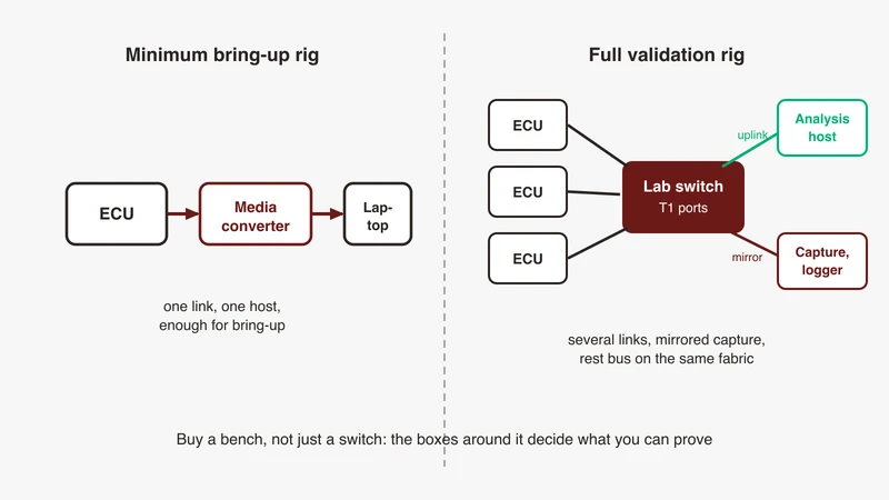
A media converter puts one automotive Ethernet link onto equipment with an RJ45 port, and our media converter selection guide covers the criteria to put to a supplier. It is not passive: it terminates the T1 channel and starts a new one, so everything downstream tells you about the converter’s Ethernet side rather than the pair. Our comparison of taps, mirror ports and converters sets out what each method preserves.
Pluggable T1 modules in a cage
A pluggable module changes the mechanics and the port density, not the physics. It still contains a T1 PHY, still holds a role, still terminates the channel at its front face, and it brings its own connector, one more family to have a mating lead for. When a bench is built around a lab switch, plan the module connectors alongside the ports.
Master and slave at the converter
Here is the mistake that looks like a cable fault. A converter or module with a T1 PHY has a master or slave setting, and it has to be the complement of the port it faces. Two masters or two slaves gives a dead link with clean continuity, which sends people to the harness. Check the roles first.
Cable faults, and what only looks like one
Polarity and pair swap on a single pair
A swapped pair is not, by itself, a reason for no link. The 802.3bw ballot text describes link-up starting with the master PHY sending symbols to the slave, during which the slave detects a polarity flip and corrects it in both its received and its transmitted signals. Continuity, shorts and breaks are the faults that stop a link.
Role misconfiguration presenting as no link
Worked in order in the bring-up checklist. It is here because it is the thing most often misdiagnosed as a cable problem.
Intermittents from strain and seating
Vibration works a partially latched connector loose, thermal cycling moves both the cable’s characteristics and the PHY’s margin, and a harness bend concentrates strain at a joint. These log errors rather than dropping cleanly, so the instrument is a trend rather than a single observation.
When to reach for a physical-layer measurement
Reach for the signal rather than the frames when a link degrades rather than failing, when the failure tracks movement or temperature, or when a channel change is the only thing that happened. Frames tell you what arrived; only the pair tells you what the channel did to it, and our guide to scoping automotive Ethernet alongside CAN FD, LIN and FlexRay covers that side of the bench. If the frames arrive and the timeline is the problem, that is a multi-bus correlation question instead.
Specifying and sourcing lab assemblies
Assemble or buy
Lab leads can be bought as assemblies or built from bulk cable and crimped contacts with the family’s tooling. Buying moves the channel evidence to the supplier and takes crimp variability off your bench. Building gives exact lengths and faster iteration, and its failure mode is a lead nobody characterised being used as reference evidence.
What to state on a purchase specification
State enough that only one thing can arrive. Connector family and variant, exactly as the supplier names it. Gender, and the coding or keying where the family has them. Shielded or unshielded, with the cable construction and conductor cross-section. Length, and whether that is mated or cut. Temperature grade and sealing. Ports or positions in the housing. The PHY rate the assembly must support, and which channel and component document the supplier claims against. Latching or position assurance where the application needs it. Quantity, and whether a first article is required.
Write those as a list rather than a bare part number, because a part number without the channel claim behind it leaves nothing to hold when an assembly behaves differently from your reference lead. Sourcing a whole bench is a wider exercise, involving qualification evidence and spares policy, and it deserves its own treatment.
Where GSAS fits
Most of the lost days we get called about are not equipment problems. An ECU arrived, the bench could not mate with it, and a week went into working out which family it carries. That is avoidable with one conversation before the units ship: which connector families your incoming devices use, what the bench has to prove about each link, and whether the channel you are building sits inside the link segment the PHY was specified against.
GSAS Micro Systems is an engineering partner, so the output of that review is often a list rather than a quotation. The mating leads to keep on the shelf. The role settings to record per link. The channel document to ask each supplier to claim against. Where the answer is that your bench already covers it, that is the answer you get.
Our field engineers work with automotive programmes from Bengaluru, Hyderabad, Chennai, Pune, Mumbai and Delhi NCR, in IST, so a session lands inside your working day. Start with the automotive Ethernet capabilities page for the overview, and request a scoped conversation to talk through a specific harness, bench or validation plan. A consultation, not a commitment.
References
- IEEE 802.3 Ethernet Working Group: https://www.ieee802.org/3/
- IEEE P802.3bw 100BASE-T1 objectives (single balanced twisted pair, EMC and temperature, at least 15 m, BER 10 to the minus 10): https://www.ieee802.org/3/bw/public/20140717_V3_Objectives.pdf
- IEEE P802.3bw D1.2 approved ballot comments (link segment of up to 15 m, four inline and two end connectors, single-pair UTP, slave polarity correction at link-up): https://www.ieee802.org/3/bw/comments/8023bw_D1_2_approved.pdf
- IEEE P802.3bp 1000BASE-T1 updated objectives: https://www.ieee802.org/3/bp/Updated_Objectives_0714.pdf
- IEEE P802.3bp D1.4 Clause 97 draft text (Type A unshielded balanced copper at least 15 m, Type B balanced copper at least 40 m): https://www.ieee802.org/3/bp/public/may15/tu_3bp_02a_0515.pdf
- IEEE P802.3ch objectives (at least 15 m, up to four inline connectors, BER 10 to the minus 12; candidate cabling types UTP, STQ, STP, SPP, coax or twinax): https://www.ieee802.org/3/ch/0317_approved_objectives_3NGAUTO.pdf
- IEEE P802.3ch ad hoc, “Editorial status of shielding in draft” (Clause 149 single shielded balanced pair; coupling and screening attenuation qualified to shielded cabling): https://grouper.ieee.org/groups/802/3/ch/public/adhoc/zimmerman_3chah_01_010820.pdf
- IEEE P802.3cy approved updated objectives (at least 11 m, up to two inline connectors): https://www.ieee802.org/3/cy/P802d3cy_OBJ_UPDATED_APPROVED_07_14_22.pdf
- OPEN Alliance specification index (100BASE-T1 Channel and Component Requirements; 1000BASE-T1 Link Segment Type A, STP and UTP, TC9; 1000BASE-T1 and 2.5G/5G/10BASE-T1 Link Segments, TC9): https://opensig.org/automotive-ethernet-specifications/
- Rosenberger H-MTD family page (source of the H-MTD and H-MTD e cells): https://www.rosenberger.com/product/h-mtd/
- Rosenberger MTD family page (source of the MTD cells): https://www.rosenberger.com/product/mtd/
- TE Connectivity MATEnet page (source of the MATEnet cells): https://www.te.com/en/products/connectors/automotive-connectors/intersection/matenet.html
Also appears in:
Building for Automotive & Mobility?
Talk to our application engineers for personalized tool recommendations.