In short
A CAN-to-Ethernet gateway carries legacy bus traffic over an IP network, either tunnelling frames unchanged for loggers and remote benches, or translating signals into services such as SOME/IP for Ethernet consumers. Tunnelling preserves the frame and moves your timing problem into the network; translation preserves the meaning and discards the frame. Ask which of the two a product does before comparing anything else about it.
Search for a CAN-to-Ethernet gateway and much of what ranks is generic industrial listings that never mention a vehicle.
The requirement did not leave with the product. Legacy buses still have to reach modern loggers, remote test PCs and Ethernet-native tooling, and on a zonal vehicle an Ethernet backbone. The deeper problem: “gateway” names two jobs with almost nothing in common, and a specification written before choosing between them buys the wrong box.
What a CAN-to-Ethernet gateway actually does
The one-line definition, and the two jobs hiding inside it
A CAN-to-Ethernet gateway moves traffic between a classic in-vehicle bus and an IP network. True, and nearly useless, because it covers two designs with different failure modes.
Job one, transport tunnelling. The frame crosses unchanged. It goes in one side and comes out the other as the payload of a UDP or TCP packet, identifier and data bytes intact, and something at the far end unwraps it into a CAN frame. The IP network is a wire.
Job two, signal-to-service translation. The frame stops at the box. The gateway decodes signals from the payload using a database and re-emits their values as arguments in a service interface, typically SOME/IP. No CAN frame appears on the Ethernet side.
One test separates them: after the box, does the CAN frame still exist as a frame? If yes, a tunnel. If no, a translator. Timing behaviour, configuration effort and failure signatures all follow.
Why the question comes up now
Vehicles now carry an Ethernet backbone alongside the classic buses, and CAN is not going anywhere, as our comparison of Ethernet and CAN sets out. Zonal architectures shorten those buses into stubs behind a zone controller that inherited the gateway role. And benches are shared: the hardware is in one lab, the engineer who needs it in another city.
The industrial world uses the same phrase for its products, another reason the results are muddled: our notes on an embedded HTTP server and on remote management for industrial gateways describe CAN-to-Ethernet gateway products on factory floors and in service bays. Same words, different constraints.
What it is not
Not a diagnostic tester: that is a different protocol with a different purpose, in our DoIP walkthrough. Not a bus analyser: a gateway moves traffic, an analyser interprets it, and capture belongs to taps and mirror ports and loggers that capture without loss. Not a lab switch, and not a media converter, which changes the physical layer and nothing else.
Job one, transport tunnelling: carry the frame unchanged
Encapsulating a frame in a UDP or TCP payload
The pattern is simple enough that open implementations exist and can be read. cannelloni describes itself as a SocketCAN over Ethernet tunnel, written in C++11, using UDP, TCP or SCTP to transfer CAN frames between two machines, with CAN FD support on interfaces that support it. The bus side is ordinary SocketCAN, the kernel’s model of CAN controllers as network devices reached through PF_CAN sockets, so a tunnel is a userspace program holding a CAN socket on one side and an IP socket on the other.
For LIN and FlexRay the route with a published specification behind it is capture encapsulation. ASAM describes its Capture Module Protocol as defining the communication between capture modules, or probes, and data sinks to monitor in-vehicle bus communication and sensor data, transported over Ethernet, and it covers CAN and CAN FD, LIN, FlexRay, Ethernet, SPI and I2C. Field layouts are in our capture encapsulation article.
What has to travel with the frame
A CAN frame is less self-describing than it looks. A tunnel carrying only the identifier and the data bytes discards most of what a debugging session needs: identifier format and remote-transmission flag, length encoding and bit-rate-switch state on CAN FD, which channel it arrived on, whether it was received or transmitted locally, whether it was an error frame, and when it was seen at the bus.
Wireshark’s CAN dissector is a good vocabulary for checking a supplier’s answer, naming the fields an analyst expects to filter on: can.flags.err for the error message flag, can.flags.rtr and can.flags.xtd for identifier format, can.bus_id for the channel, and canfd.flags.brs and canfd.flags.esi on the FD side. A field that cannot survive the tunnel cannot be filtered at the far end.
Per-frame datagrams versus batching
This decision sets the latency of a tunnel, and cannelloni documents its side clearly. It sends either a full UDP frame or all the CAN frames queued when a configurable timeout expires; the default is 100000 microseconds, and the README gives the worst case for any frame as roughly that timeout plus Ethernet latency plus delay on the receiver. High-priority identifiers can be given shorter timeouts through a CSV table, and the whole buffer is then flushed, not only the listed frames.
The trade is not subtle. One datagram per frame gives the lowest delay and worst overhead ratio; batching amortises the headers and adds a queueing delay bounded by the timeout. No configuration avoids both, and a product claiming otherwise is either sending per-frame datagrams without saying so, or batching without telling you the timeout. On TCP the question changes shape: cannelloni states that with TCP no frame buffer is used and frames go immediately, so sorting and timeouts do not apply.
The same README is candid where a datasheet will not be: cannelloni is not suited for production deployments, should be used only where packet loss is tolerable, and gives no guarantee that frames reach their destination at all or in the right order. It also names a failure worth putting to a vendor: it applies a staleness timeout, default 2000000 microseconds, after which an undeliverable frame is dropped rather than buffered, because a physically broken bus, unterminated or floating, may never reach an error state, and a naive implementation buffers as long as the fault lasts, then floods the bus on recovery.
Why the timestamp must be applied before the tunnel, not after
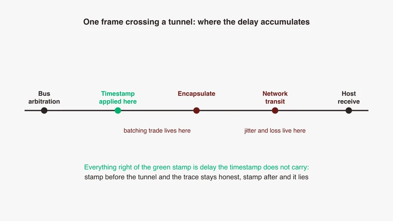
The cannelloni README documents aggregation, transports, timeouts and frame sorting, and no per-frame timestamp, which is why the encapsulated-capture formats exist. A timestamp taken when your host receives the IP packet measures the network, not the bus. Between the two sit arbitration, gateway processing, batching delay, network transit and host scheduling, none of them constant.
The Linux kernel timestamping documentation is precise about the general case: software receive timestamps are generated just after a device driver hands a packet to the kernel receive stack, while hardware receive timestamps are generated by the network adapter. Everything after the point of stamping is inside the number. SocketCAN documents a CAN timestamp obtained with an ioctl after reading from the socket, at one microsecond resolution, and resolution is not accuracy.
So a tunnel stamping at the bus end preserves an ordering claim and one stamping at the host end does not, the same argument from the other side as our article on correlating CAN, LIN, FlexRay and Ethernet traces.
Job two, signal-to-service translation: change the representation
Signals in a database becoming methods, events and fields
The second job changes representation, not transport. A classic bus is signal oriented: values sit in fixed slots in fixed frames at fixed rates, frozen at design time in a database. A service interface is not: a provider offers a service, a consumer discovers it at runtime, and communication is expressed as methods, events and fields, as our SOME/IP explainer covers. A translating gateway decides, per signal, whether it appears at all, in which service, as which member, and how often.
Cycle-driven signals meeting event-driven services
The mismatch that catches teams out is temporal. A signal updating every 10 milliseconds whether or not it changed is a fine control-loop input and a poor event source: forwarded literally it produces a hundred notifications a second, most identical.
Three usual policies, each wrong somewhere. Forward every cycle, and you move a cyclic load onto a network chosen partly to escape it. Forward on change, and consumers lose the liveness a repeated value carried, so a stuck sensor and a stable value look alike. Forward on change with a keepalive, usually right, and the one needing a decision per signal rather than a global switch.
The standard specifies the mechanism, your configuration carries the decisions
AUTOSAR is often assumed to answer this. It answers half. The Classic Platform Specification of SOME/IP Transformer, document 660, specifies a transformer that linearizes data with the SOME/IP on-the-wire format and specifies an automotive and embedded mechanism for client and server communication. That is the serialization mechanism, tightly defined.
On its own configuration the document is explicit: the SOME/IP Transformer has no module specific EcuC because its whole configuration is based on the SOMEIPTransformationDescription and the per-signal SOMEIPTransformationISignalProps. In which interface version, with which message type and which length-field sizes, is attached to individual signals through SOMEIPTransformationISignalProps; byte order is set once on the transformer’s SOMEIPTransformationDescription. Neither class expresses which signal becomes which argument of which service: that decision lives outside this specification. The standard says how to serialize once that decision is made. It does not make it.
Published work reflects the same division. Oh and colleagues, in Electronics 12(13) 2777, describe a CAN and Ethernet gateway on a TC275 microcontroller and distinguish three routing methods: frame-based, where a message reaches another network with only its frame format translated, and the PDU-based and signal-based routing their gateway implements. On the mapping itself the paper is plain about its own experiment: the routing rules were chosen arbitrarily for experimentation. In a prototype that is a fair simplification; in a programme it is the artefact deciding whether two teams agree about what the vehicle means. The same paper measured its gateway’s average end-to-end processing time at 421 microseconds against a worst case of 793 in its uncompressed baseline, and 336 against 703 once its data-reduction algorithm was applied. Not a product figure, and not a service-translation figure either, but the roughly two-to-one spread between average and worst case is worth carrying away.
Where the mapping decisions get made, and why they end up undocumented
In a spreadsheet, in a configuration dialog, or between two engineers who have both left the programme. The output is a generated configuration, correct by construction and unreadable by intention, with the reasoning behind it nowhere inside. Treat the mapping as source: version it, review it as you review code, keep a plain-language rationale beside it.
What tunnelling costs you
Added latency and, more importantly, added jitter
Everyone expects delay; the variance is what surprises. Added delay is the sum of gateway processing, any batching interval, network transit and host handling, and the last three are load dependent, so an average that looks harmless sits beside a much larger worst case. Jitter decides whether a measurement is defensible: ordering claims turn on the sign of a difference, and a difference smaller than your jitter cannot be signed.
Ordering and loss: what UDP and TCP actually promise
Both failures arrive as timing. UDP has no delivery or ordering guarantee, and a dropped datagram is a gap that looks like a quiet bus. cannelloni’s own usage notice covers every transport it offers, not only UDP: no guarantee that frames arrive at all or in order. TCP delivers in order and pays with retransmission, so a lost segment becomes a delay wearing the costume of gateway or ECU processing time. For observation, a loss you can detect through sequence numbers is more honest than a delay you cannot attribute.
Bandwidth expansion, and when delay changes the behaviour under test
A classic CAN frame carries up to 8 data bytes, and wrapped individually in Ethernet, IP and UDP headers the useful fraction is small. Oh and colleagues note the floor: the Ethernet minimum frame length of 64 bytes exceeds a single CAN data field of 8 bytes, which is why it is possible to include several protocol data units in one Ethernet message at no extra cost on the wire. On a lab link nobody cares; over a shared corporate path, this is the number that becomes a conversation with the network team.
Then a line worth drawing carefully. Observation delay changes your view of the system; loop delay changes the system. A tunnel carrying frames outward to a logger degrades your measurement and leaves the device under test alone. A tunnel inside a loop the device can detect, a rest bus simulation with a response window or a fault injection timed against a frame, is part of the behaviour. A timeout that appears only when the test runs over a tunnel is not a finding about the ECU.
Fine for logging, observation and remote monitoring; not fine without measurement for rest bus simulation, fault injection and closed loops.
Pick the right kind of gateway
| Use case | Tunnelling or translation | Timing sensitivity | What to verify before buying |
|---|---|---|---|
| Remote bench access from another site | Tunnelling | Moderate: observation tolerates delay, control does not | Where the timestamp is applied, batching timeout, loss behaviour |
| Multi-bus logging into one capture | Tunnelling, ideally encapsulated capture | High: cross-bus ordering is the deliverable | One clock across all channels, a synchronisation flag you can filter on, a format your tools read |
| Bus extension across a lab | Tunnelling | Moderate to high | Sustained frame rate rather than peak, error frame and bus-off propagation, behaviour on a broken far bus |
| Legacy ECU on an Ethernet backbone | Translation | High: production timing behaviour, not a measurement | Per-signal mapping and update policy, configuration export, what happens to signals with no service equivalent |
| Rest bus simulation | Usually neither, run it local to the bus | Very high: the gateway is inside the loop | Measured round-trip delay and jitter against the response deadline |
| Diagnostics over IP | Neither, this is a diagnostic transport | Session-level, not frame-level | That the requirement really is diagnostics, see below |
That last row is the recurring mistake. DoIP is the transport standardised as ISO 13400 that carries UDS diagnostic messages over automotive Ethernet, with vehicle discovery, a routing activation handshake and logical addressing, as our DoIP article walks through phase by phase. It is not a bus tunnel, and a DoIP session will never show the cyclic CAN traffic flowing while you are connected. Teams specify a DoIP-capable interface, find no bus frames, and conclude the hardware is faulty.
Reaching a test rig from another site
Latency budget over a corporate network versus a lab switch
A lab switch is a known quantity: short path, one hop, load you control. A corporate network carries traffic you cannot see, may cross a VPN concentrator, and changes its delay distribution with the working day. The question is not how fast the link is but what the worst case is and how often, so measure the distribution across a full working day before planning a campaign on it. Our note on how Ethernet sits in the vehicle communication architecture covers the in-vehicle side.
Security posture and clock discipline
A remote bench tunnel is a route from a general-purpose network into one that expects physical protection. The buses at the far end were designed with no authentication, and a frame injected over your tunnel is indistinguishable from one produced by an ECU. The question at specification time is who can reach the endpoint, with what credential, and whether anybody would know afterwards.
Two sites also mean two clocks unless somebody has related them. Stamp at the bus end and cross-site drift affects only correlation with records at the remote end; stamp at the host and that drift goes straight into your measurement, where it supports no ordering claim.
Four guardrails cost little and are hard to retrofit: a dedicated VLAN rather than the office subnet; routing restricted to named hosts; authenticated and logged access, so a session can be attributed afterwards; and the tunnel port kept off any interface facing a wider network than it needs.
Selection checklist and the pitfalls that recur
- Timestamp source and resolution, asked explicitly. Where is the stamp applied, on what clock, and what disciplines that clock? A one-microsecond resolution field says nothing about accuracy, and a stamp landing at the receiving host makes the product a transport, not an instrument.
- Frame rate under sustained load, not a peak figure. Frames per second across all channels at once, held for minutes, and what happens when that is exceeded: drop, buffer, or block the bus. The failure mode matters more than the number.
- Error frame and bus-off visibility. Controller state is what you need most on a bad day and what thin encapsulations discard first. If the far end cannot filter on the error flag, those events were not carried.
- Direction and echo handling. SocketCAN enables loopback by default, with
MSG_CONFIRMon reception indicating the frame was sent via the socket it is received on. Any tunnel decides whether echoes cross it, and the analysis has to know which way, or a transmitted frame gets debugged as a received one. - Configuration export. Mapping, filters, timeouts and channel assignment should come out as a readable file for version control. A setup existing only in a GUI gets rebuilt from memory.
- Bench connector and cabling reality. The tunnel does not fix the physical layer at either end: the automotive Ethernet side has its own connector families, in our cables and connectors guide, and the bus side still needs correct termination. When a link will not come up, the 100BASE-T1 checklist beats blaming the gateway.
Where GSAS fits
Most conversations we have about gateways open with a product comparison and end somewhere else, because the first question, tunnelling or translation, has not been settled. The two lead to different hardware, configuration effort and acceptance criteria, so a comparison across that boundary is not a comparison. We help teams settle it first, using the bench they have and the traces they already collected.
Where a purchase does follow, the questions we help put to a supplier are the ones in this article: where the timestamp is applied and on what clock, sustained frame rate rather than peak, what happens to error frames and controller state, and whether the configuration exports. Production-line ECU programming is a different discipline with different equipment, and we treat it separately.
Our field engineers work with automotive programmes from Bengaluru, Pune, Chennai, Hyderabad, Mumbai and Delhi NCR. For a review of a remote bench topology, or a second opinion before a gateway is specified, our automotive Ethernet capabilities page is the overview and request a quote starts the conversation. A consultation, not a commitment.
References
- cannelloni, a SocketCAN over Ethernet tunnel, project README: https://github.com/mguentner/cannelloni
- Linux kernel networking documentation, SocketCAN: https://docs.kernel.org/networking/can.html
- Linux kernel networking documentation, Timestamping: https://docs.kernel.org/networking/timestamping.html
- ASAM CMP, Capture Module Protocol, standard page: https://www.asam.net/standards/detail/cmp/
- AUTOSAR Classic Platform R24-11, Specification of SOME/IP Transformer, document 660: https://www.autosar.org/fileadmin/standards/R24-11/CP/AUTOSAR_CP_SWS_SOMEIPTransformer.pdf
- Oh, S.B.; Do, Y.S.; Lee, M.J.; Kim, J.H.; Jeon, J.W. “Performance Enhancement of CAN/Ethernet Automotive Gateway with a CAN Data Reduction Algorithm”, Electronics 2023, 12(13), 2777: https://doi.org/10.3390/electronics12132777
- Wireshark display filter reference, CAN protocol fields: https://www.wireshark.org/docs/dfref/c/can.html
Also appears in:
Building for Automotive & Mobility?
Talk to our application engineers for personalized tool recommendations.