
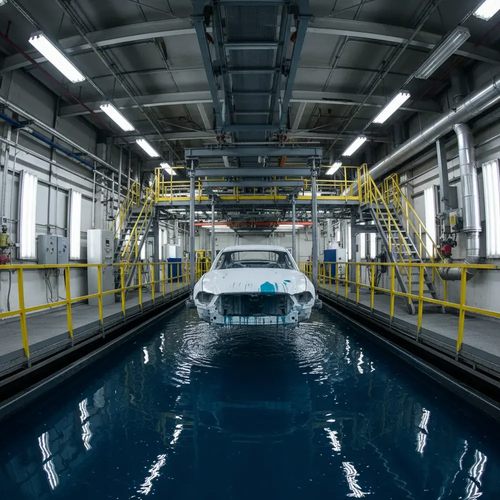
Electrocoating, e-coat, is the first paint layer applied to every automotive body-in-white (BIW). It provides the primary corrosion barrier that determines whether a vehicle’s body lasts five years or fifteen. The process is elegant in principle: immerse the steel body in a tank of charged paint particles, apply voltage, and electrochemistry deposits a uniform coating on every surface.
In practice, the physics is adversarial. Recessed areas, closed box sections, and overlapping panels create Faraday cage effects that starve inner surfaces of coating. Elsyca’s ECoatMaster creates a digital twin of the entire e-coat process, predicting thickness distribution across every surface of the BIW and enabling optimization before a physical body ever enters the tank.
The E-Coat Process
After phosphate pretreatment, the BIW is immersed in a tank containing waterborne epoxy resin particles carrying negative charge. The body is connected as the cathode. Anodes line the tank walls and are inserted into critical body cavities. When voltage is applied (200 to 400 V), paint particles migrate toward the body and deposit. The electrochemical reaction creates a resistive barrier as coating builds up, a self-limiting mechanism that makes e-coat theoretically self-levelling.
In theory, this produces uniform coating. In practice, it does not.
The Faraday Cage Problem
A car body is a collection of overlapping steel panels, closed box sections, hemmed flanges, and spot-welded joints. These features create regions where the electric field cannot penetrate.
Closed box sections. The interior of an A-pillar or rocker panel is a near-perfect Faraday cage. The surrounding steel shields the interior from the electric field, leaving these surfaces with minimal coating, precisely where standing water collects and corrosion begins. Overlapping panels. Narrow gaps between overlapping panels attenuate the electric field. These gaps trap moisture through capillary action, making them corrosion initiation sites. Deep recesses. Floor pans, wheel arch interiors, and structural cross-members sit farther from tank anodes, receiving less current and thinner coating. Weld nuggets and sharp edges. Spot-weld protrusions attract excess current, building up coating on the nugget while the adjacent heat-affected zone remains thin.
How ECoatMaster Works
ECoatMaster models the complete physics in a three-dimensional digital twin.
Geometry import. The simulation ingests the full BIW CAD model plus tank geometry, walls, anode positions, entry/exit ramps, auxiliary anodes. The mesh resolves critical features like gap openings, drain holes, and weld flanges. Physics simulation. The solver computes three coupled phenomena: primary current distribution (electric field between anodes and body), paint transport (electrophoresis plus convection), and film growth kinetics (dynamic resistance feedback as coating builds). The simulation predicts final thickness after the full 120 to 240 second immersion cycle. Thickness maps. The output is a colour-coded map projected onto the BIW surface. Every square centimetre shows predicted coating thickness. OEM specifications typically require 18 to 22 micrometres on outer surfaces and 8 to 12 micrometres on inner surfaces. Red zones indicate surfaces below minimum specification.
Optimization Strategies
With the digital twin in place, ECoatMaster enables optimization without physical trials.
Auxiliary anode placement. Electrode probes inserted into body cavities through drain holes are the most direct way to coat Faraday cage interiors. ECoatMaster simulates different positions, shapes, and voltages, evaluating dozens of configurations in hours versus weeks of physical trials. Drain hole optimization. Every closed section needs drain holes. Their size, shape, and position affect how much current reaches cavity interiors. ECoatMaster finds the minimum hole size that provides adequate coating, important because larger holes compromise structural stiffness and NVH performance. Voltage profile optimization. A ramped voltage profile, starting low and increasing, can improve uniformity by allowing initial coating on easy-to-reach surfaces before driving current into harder areas. Body path optimization. The angle and speed of BIW entry and exit affects which surfaces are immersed first and for how long. ECoatMaster simulates different angles and dwell times for programmable pendulum or C-hook conveyors.
Indian Automotive OEM Context
India is the world’s third-largest automobile market by volume. Every one of those vehicles has an e-coated body. Indian OEMs, Maruti Suzuki and other major domestic auto manufacturers, and Indian plants of global OEMs all operate e-coat lines.
Climate severity. India’s coastal and tropical regions subject vehicle bodies to extreme humidity, salt air, and temperature cycling. Corrosion protection is not optional. Model proliferation. Indian plants produce multiple body styles on shared lines, each with different geometry and coating requirements. Reoptimizing through physical trials for each model is prohibitively slow. EV body structures. Electric vehicle platforms introduce novel e-coat challenges, battery tray cavities are particularly difficult to coat uniformly due to their flat, closed geometry. Sustainability pressure. Overcoating wastes energy and paint material. ECoatMaster optimization reduces both by minimizing the voltage and time needed to achieve specification.
From Simulation to Production
During vehicle development, the BIW CAD model goes to ECoatMaster months before the first prototype. Results feed back to body engineering for drain hole optimization and to manufacturing engineering for process parameter specification. During production, ECoatMaster validates that the process delivers predicted results. Cross-section measurements from early production bodies calibrate the model, creating a living digital twin that tracks the process over time, accounting for anode wear, bath ageing, and seasonal temperature variation.
Engaging with GSAS for ECoatMaster
GSAS Micro Systems represents Elsyca’s complete simulation portfolio in India, including ECoatMaster, CorrosionMaster, and the PCB simulation tools. For a first engagement, we recommend a pilot: simulate a single body cavity using your CAD data and process parameters, then cross-section the same cavity on a physical body. The correlation demonstrates accuracy and builds confidence for full-vehicle deployment.
Reach out to GSAS at gsasindia.com to discuss how ECoatMaster fits into your corrosion protection strategy.
Also appears in:
Interested in Elsyca tools?
Talk to our application engineers for personalized tool recommendations.
More from Elsyca
View all →
Elsyca PCBPlate: How Panel Plating Simulation Predicts Copper Thickness Before Fabrication
5 Apr · 6 min

Elsyca PlatingManager: Digital Twin Simulation for Industrial Electroplating Lines
4 Apr · 5 min

Copper Thieving for PCBs: Why Manual Methods Fail and How Simulation Fixes It
3 Apr · 5 min
Via Plating Reliability: Why Thin Barrels Fail and How Simulation Prevents It
2 Apr · 5 min

Emulating Processor Power for Thermal Testing: Why Constant Power
7 Oct · 7 min

CRPS and Rack Power Supply Testing: The Six Tests That Matter
7 Oct · 7 min


