
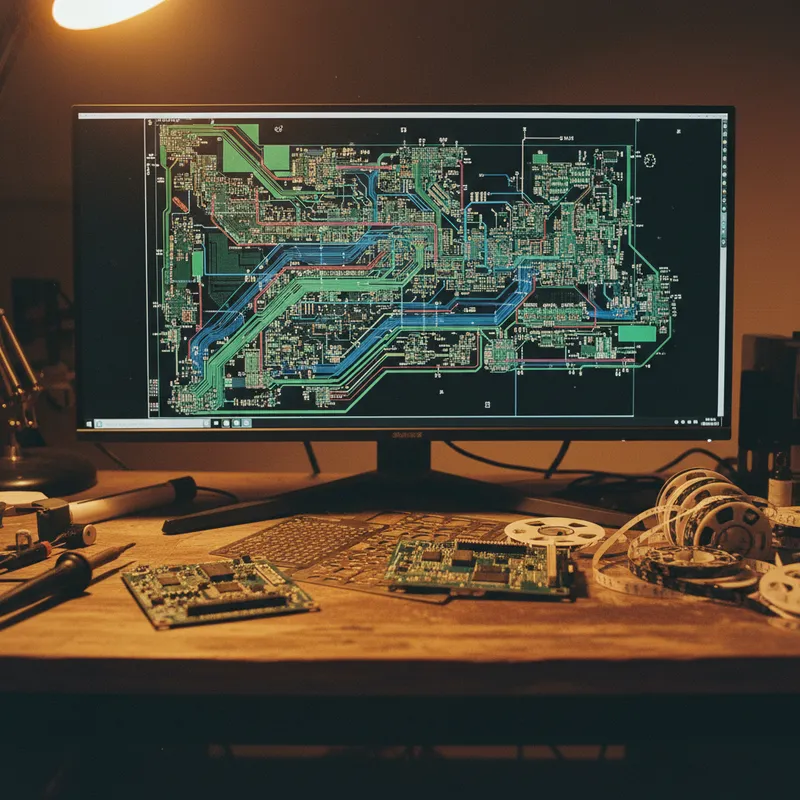
Copper electroplating is the process that transforms etched PCB patterns into functional circuit boards, depositing copper onto trace surfaces, filling plated-through holes, and building up the conductor thickness that determines current-carrying capacity, impedance, and reliability. When this deposition is uniform, the board meets specification. When it is not, the consequences cascade through the product: controlled-impedance traces shift outside tolerance, thin via barrels crack under thermal cycling, and overplated edges bridge adjacent conductors.
Elsyca PCBPlate addresses this problem at its root by simulating the electrochemical plating process before a single panel enters the plating line. The software predicts copper thickness distribution across the entire panel, every trace, every pad, every via, based on the actual physics of current distribution, ion transport, and reaction kinetics in the plating cell. Validated by Eurocircuits with measured accuracy exceeding 90% compared to physical cross-section measurements, PCBPlate converts plating prediction from guesswork into engineering.
The Physics Behind Plating Non-Uniformity
Electrochemical deposition follows Faraday’s law: the mass of copper deposited is proportional to the local current density. The challenge is that current density is not uniform across the panel, it is governed by the geometry of the panel, the plating cell, and the copper patterns themselves.
Primary current distribution is determined by the geometry of the electrodes (anode and cathode/panel) and the resistivity of the electrolyte. Points on the panel closer to the anode, or with less obstructed current paths, receive higher current and plate faster. Panel edges typically plate 30-50% thicker than panel centres.
Secondary current distribution accounts for the electrode kinetics, the overpotential relationship at the copper surface. The addition of organic additives (levellers, brighteners, carriers) modifies the electrode kinetics to improve throwing power and reduce thickness variation.
Tertiary current distribution incorporates mass transport, the diffusion of copper ions through the boundary layer at the electrode surface. In high-current regions or deep vias where ion depletion occurs, mass transport becomes the limiting factor, and the plating rate drops below what the current distribution alone would predict.
PCBPlate models all three distribution regimes, primary, secondary, and tertiary, providing a complete physics-based prediction that accounts for panel geometry, cell geometry, bath chemistry, flight bar position, and anode configuration.
How PCBPlate Works in Practice
The workflow is straightforward:
- Import Gerber files: PCBPlate reads Extended Gerber (RS-274X) data for all layers of the panel layout
- Define the plating cell: specify anode geometry, anode-to-panel distance, flight bar position, and current density
- Configure bath chemistry: select the plating bath type (acid copper, pulse plating) and additive system
- Run the simulation: PCBPlate solves the electrochemical equations across the panel geometry
- Analyse results: 3D copper thickness maps show where the panel will plate thick and thin
The output is not abstract, it is a quantitative prediction of copper thickness at every point on the panel, expressed in micrometres. Engineers identify areas that will fall below minimum thickness specification and areas that will overplate, then take corrective action before production.
Corrective Actions Enabled by Simulation
PCBPlate enables several corrective strategies:
Flight bar optimisation. The position and contact configuration of the flight bar (the mechanical holder that clamps the panel and conducts plating current) significantly affects current distribution. PCBPlate evaluates alternative flight bar positions to find the configuration that produces the most uniform current distribution.
Panel layout optimisation. The arrangement of boards on a production panel affects plating uniformity. PCBPlate predicts the impact of different panel layouts, board rotation, border spacing, dummy patterns, on copper thickness distribution.
Process parameter tuning. Current density, plating time, pulse waveform, and additive concentration all influence thickness uniformity. PCBPlate enables virtual experimentation with process parameters before committing to physical trials.
Integration with PCBBalance
While PCBPlate simulates the plating process itself, Elsyca PCBBalance works at the design stage, automatically generating copper thieving and balancing features that equalise copper density across each layer. The two tools are complementary:
- PCBBalance optimises the copper pattern for uniform plating (design-stage DFM)
- PCBPlate validates the plating outcome for the optimised panel (process-stage verification)
This two-stage workflow catches plating problems first at the design level (copper pattern) and then at the process level (plating cell configuration), providing comprehensive plating quality assurance.
The India PCB Manufacturing Context
India’s PCB manufacturing sector is expanding under Make in India and PLI incentives, with fabrication facilities in Bengaluru, Pune, Chennai, Delhi NCR, and other centres investing in higher-layer-count, tighter-tolerance production capability. As Indian fabricators move from 4-6 layer commodity boards to 10+ layer HDI designs with controlled impedance and fine-pitch features, plating uniformity becomes a yield-critical parameter.
Indian PCB designers working with domestic and international fabricators benefit from PCBPlate simulation by identifying plating risks before submitting designs for production, reducing re-spins, improving first-pass yield, and shortening the design-to-production cycle.
Why Buy from GSAS
GSAS provides Elsyca PCBPlate and PCBBalance licensing in India with INR invoicing, training, and application support. Our team helps PCB design and manufacturing organisations in Bengaluru, Hyderabad, Chennai, Pune, Mumbai, Delhi NCR, and Visakhapatnam establish plating simulation workflows.
Explore PCBPlate → | Explore PCBBalance → | Request a Quote →
Also appears in:
Interested in Elsyca tools?
Talk to our application engineers for personalized tool recommendations.
More from Elsyca
View all →
Elsyca PlatingManager: Digital Twin Simulation for Industrial Electroplating Lines
4 Apr · 5 min

Copper Thieving for PCBs: Why Manual Methods Fail and How Simulation Fixes It
3 Apr · 5 min
Via Plating Reliability: Why Thin Barrels Fail and How Simulation Prevents It
2 Apr · 5 min
E-Coat Simulation for Automotive Bodies: Eliminating Bare Spots Before Production
1 Apr · 5 min

Emulating Processor Power for Thermal Testing: Why Constant Power
7 Oct · 7 min

CRPS and Rack Power Supply Testing: The Six Tests That Matter
7 Oct · 7 min

