
USB-C has become the universal connector for consumer electronics, and India’s cable manufacturing industry is producing millions of USB-C cables annually for domestic consumption and export. But USB-C is not a simple cable, it is a complex assembly with specific electrical requirements that, if not met, can cause device damage, charging failures, and safety hazards. The testing requirements for USB-C cables go well beyond the continuity checks sufficient for legacy USB cables.
Why USB-C Testing Is More Complex
A USB-C connector has 24 pins, far more than the 4 pins of USB-A or the 5 pins of Micro-USB. The cable carries power delivery up to 240 W (48 V / 5 A in the latest USB PD 3.1 specification), high-speed data (USB 3.2 at 20 Gbps, USB4 at 40 Gbps), and alternate mode signals (DisplayPort, Thunderbolt). The Configuration Channel (CC) pins carry critical information about cable capabilities, and many cables include an e-marker chip that communicates cable ratings to the connected devices.
A USB-C cable with incorrect CC resistor values can cause a device to draw more current than the cable can safely handle, a fire hazard. A cable missing its e-marker chip will be limited to 3 A by compliant devices, even if the cable is physically capable of more. A cable with incorrect wiring between the two connectors can damage connected devices.
Key Test Parameters
| Test | What It Verifies | Consequence of Failure |
|---|---|---|
| CC Resistance | Configuration Channel pull-up/pull-down values | Device may draw unsafe current |
| e-Marker Verification | Electronic marker chip presence and data | Cable limited to 3A, or rejected by device |
| Continuity | All 24-pin connections correct | Open pins, signal failure |
| Insulation Resistance | Pin-to-pin and pin-to-shell isolation | Short circuits, EMI, safety hazard |
| Wire Resistance | VBUS and GND conductor resistance | Voltage drop, overheating at high current |
| Hipot | Dielectric withstand between power and signal | Safety compliance failure |
| Shielding | Shield continuity and coverage | EMI emission and susceptibility |
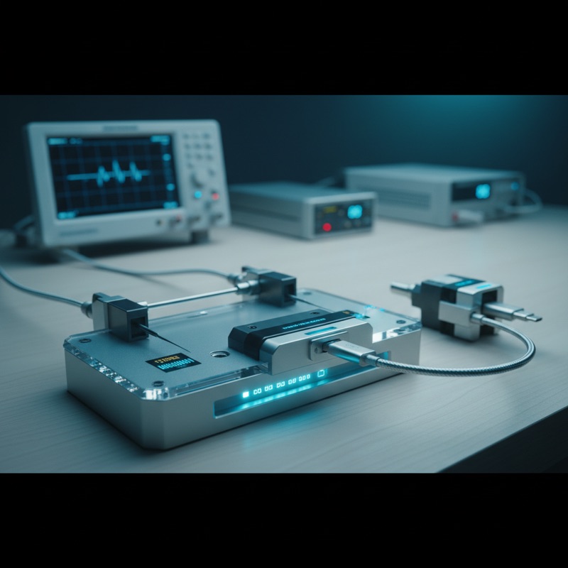
The Microtest USB-C Cable Tester performs this complete parameter set in an automated sequence, verifying both the physical wiring and the electronic marker compliance of USB-C cables.
CC Resistance: The Critical Safety Parameter
The CC (Configuration Channel) pins on a USB-C connector use specific resistor values to communicate cable type and current capability:
- 56 kohm pull-up: identifies the cable as a default USB connection (500 mA / 900 mA)
- 22 kohm pull-up: identifies the cable as capable of 1.5 A
- 10 kohm pull-up: identifies the cable as capable of 3 A
A cable with an incorrect CC resistor, for example, a 10 kohm resistor on a cable that can only handle 1.5 A, tells the connected device it is safe to draw 3 A. The cable overheats, the insulation degrades, and in severe cases, the cable or connected device catches fire.
Testing the CC resistance to the correct value is not optional for any responsible USB-C cable manufacturer. The Microtest USB-C tester measures CC resistance as part of its standard test sequence, flagging cables with out-of-spec values as safety failures.
e-Marker Verification
USB-C cables rated for 5 A or higher, and all cables supporting USB 3.2 or USB4 data rates, must contain an e-marker (electronically marked) chip. The e-marker is a small IC in the connector that stores cable capability data, current rating, data rate support, cable length, and manufacturer information. Connected devices query the e-marker over the CC channel to determine what the cable supports.
A cable without an e-marker when one is required will be limited to 3 A by compliant devices, regardless of the cable’s physical current capacity. A cable with incorrect e-marker data may misrepresent its capabilities.
The Microtest USB-C tester reads and verifies e-marker data, confirming that the stored cable capability matches the actual cable construction.
Production Testing Workflow
For Indian cable manufacturers in Delhi NCR, Pune, and Mumbai producing USB-C cables at volume, the test workflow integrates into the production line:
- Operator loads cable into the test fixture (USB-C connectors seat into standardised receptacles)
- Barcode scan identifies the cable SKU and loads the corresponding test program
- Automated test sequence executes: CC resistance, e-marker read, continuity (all 24 pins), insulation resistance, wire resistance (VBUS/GND), hipot
- Pass/fail verdict with specific failure mode identification
- Pass: cable proceeds to packaging. Fail: cable routes to reject bin with failure data logged
The entire sequence takes seconds per cable, enabling production-speed testing without sacrificing test coverage. SPC data logging tracks trends in CC resistance, wire resistance, and insulation resistance across production runs, flagging process drift before it causes batch failures.
USB-IF Compliance and Export Markets
The USB Implementers Forum (USB-IF) operates a compliance programme for USB-C cables. Cables bearing the USB-IF certification logo must pass specified electrical and mechanical tests. For Indian cable manufacturers exporting to markets that require USB-IF compliance (major consumer electronics brands, retail chains), the testing performed by the Microtest USB-C tester covers the key electrical parameters in the USB-IF test specification.
While the Microtest tester handles the electrical verification, mechanical testing (connector durability, insertion force, cable bend) requires additional test equipment. The electrical tests, however, are the most critical for safety and interoperability.
Beyond USB-C: Full Cable Testing Capability
The Microtest USB-C tester is part of a broader cable and harness testing portfolio. For manufacturers producing USB-C alongside other cable types, HDMI, DisplayPort, Ethernet, automotive harnesses, the Microtest 4-Wire Harness Tester and 2-Wire Tester cover the full range of cable testing requirements.
Why Buy from GSAS
GSAS Micro Systems is an authorised Microtest partner in India, providing USB-C cable testers and complete cable test solutions with INR invoicing. Our team supports test fixture setup, test sequence programming, and USB-IF compliance guidance for cable manufacturers across Bengaluru, Hyderabad, Chennai, Pune, Mumbai, and Delhi NCR. Contact GSAS to schedule a demo or discuss your cable testing requirements.
Also appears in:
Interested in Microtest tools?
Talk to our application engineers for personalized tool recommendations.
More from Microtest
View all →
Power Measurement for Server PSUs: Microtest 7140 Power Analyzer
7 Apr · 5 min

Wireless Charger QC Testing with the Microtest 9901
7 Apr · 5 min

Motor Stator Testing in EV Manufacturing: Microtest MT-6910 Series
7 Apr · 5 min
PCB Incoming Inspection with Multichannel LCR Testing
6 Apr · 5 min

Emulating Processor Power for Thermal Testing: Why Constant Power
7 Oct · 7 min

CRPS and Rack Power Supply Testing: The Six Tests That Matter
7 Oct · 7 min


