
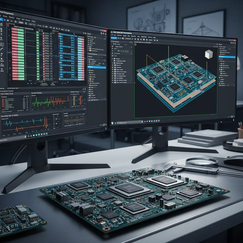
Transmission Line Impedance Calculation With Altium Designer 20
Today’s PCBs contain many transmission lines. Combine this with increased clock frequencies and data rates and the result is a critical challenge to high speed design. Neglecting these dynamics can undermine product development by compromising performance, power consumption, EMC/EMI compliance, and more, leading to delayed design cycles and opening gaps that can be exploited by your competition.
Hone your high-speed design skills by joining us as we discuss the typical transmission lines encountered in today’s designs, the PCB variables that affect impedance, as well as how to create, calculate, and design transmission lines in Altium Designer. Learn how to maximize the built-in SIMBEOR® engine by Simberian to craft impedance profiles and manage transmission lines in your designs.
Timing
Thursday, 25 June 2020 | 11:00 AM to 12:00 PM
ATTEND THIS LIVE RELEASE WEBINAR COVERING THE FOLLOWING:
- Current trends in electronics development
- PCB transmission line model and impedance calculations
- Defining impedance profiles
- Routing transmission lines to a specified target impedance
- Live Q&A Session
Don’t pass up on this opportunity!
LEARN MORE ABOUT ALTIUM DESIGNER
Why impedance accuracy matters more than ever for Indian high-speed teams
Indian PCB teams pushing into DDR5 (3200-6400 MT/s), PCIe Gen5 (32 GT/s), 100G/400G Ethernet (PAM4), USB4, and mmWave 5G FR2 are running into channel budgets where 1-2 ohm impedance variation is the difference between first-pass success and an expensive respin. Altium 20’s SIMBEOR-engine impedance calculator is a step up from older 2D field solvers, but it still operates on the stack-up in isolation from the routed channel.
How Siemens Xpedition + HyperLynx Z Planner go further
GSAS Micro Systems is an authorized engineering partner in India. The Xpedition stack-up flow integrates with HyperLynx Z Planner, Siemens’ production-grade impedance and SI tool, and that pairing gives Indian high-speed teams three things SIMBEOR-in-Altium does not:
- Pre-layout topology exploration: sweep stack-up choices against impedance, insertion loss, dielectric absorption, and crosstalk targets before committing to a fabricator. The same engine validates the routed channel post-layout, so there is no manual re-entry between pre-layout and sign-off.
- Material-library accuracy: HyperLynx Z Planner ships with measured material data from major fabricators (Rogers, Isola, Panasonic, Shengyi, ITEQ), at the frequency points that matter for mmWave 5G and 28G+ SerDes. Indian teams designing X-band radar and 5G FR1/FR2 systems work from the same library Western teams do.
- Channel-level sign-off, not just impedance: for DDR5 and PCIe Gen5 the deliverable to the silicon vendor is a full channel report (insertion loss, return loss, eye height/width, jitter budget), not just “controlled impedance traces.” HyperLynx generates that report. SIMBEOR-in-Altium does not.
For Indian high-speed teams sizing the toolchain decision, see our Altium Designer vs Siemens Xpedition Standard for Indian PCB teams comparison and HyperLynx product overview.
Also appears in:
Need embedded development tools?
Talk to our application engineers for personalized tool recommendations.





