
 ProT Ar-Ge
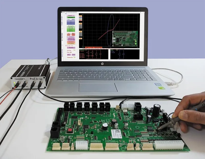
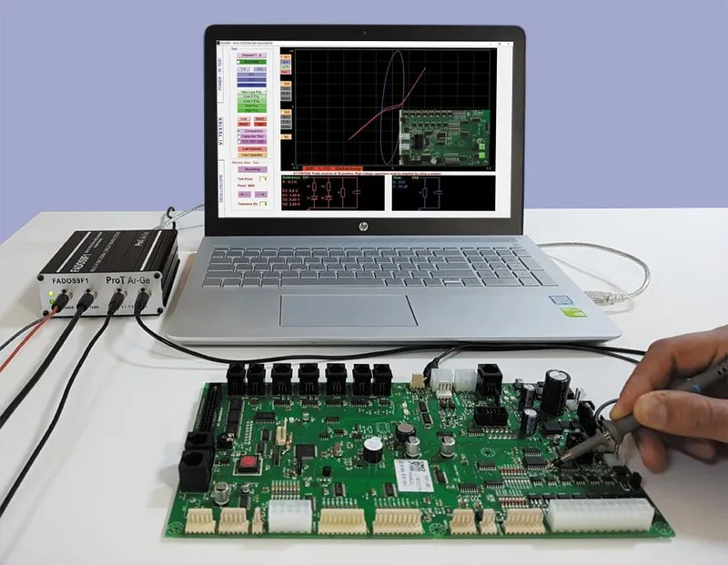
 FADOS XI Advanced VI Analyzer
Board Diagnostic SystemsAdvanced multi-functional circuit board tester with non-contact short circuit detection sensor, 3D frequency scanning (50-2500 Hz), dual-channel VI curve tracing, equivalent circuit diagram, IR thermal sensor, and powered board testing. Buy in India from GSAS.
Testing Method
VI Curve Tracing + Short Circuit Detection + Frequency Scan
Short Circuit Finder
Non-contact current sensor (FADOS XI exclusive)
Frequency Scan
50–1250 Hz (Range 1) / 100–2500 Hz (Range 2), step-by-step 3D analysis
Channels
2 (dual-channel simultaneous comparison)
Power Supply
100 mV to 16 V at 10 mA to 1500 mA, with DC V-I graph
IR Sensor
Non-contact infrared, to approx. 120 °C above ambient
Equivalent Circuit
Auto-generated R/C/L/D diagram with measured values
Dimensions / Weight
125 mm L x 113 mm W x 40 mm H, 1500 grams approx.
Software
FADOS Analysis Suite (Windows PC over USB), Excel/JPG reporting
Overview
About FADOS XI Advanced VI Analyzer
The FADOS XI Advanced VI Analyzer is the latest and most capable circuit board diagnostic system from ProT Ar-Ge, building on the proven FADOS 9F1 platform with two breakthrough capabilities: a non-contact short circuit detection sensor and step-by-step frequency scanning with 3D VI curve visualisation.
FADOS stands for FAult Detector OScilloscope, a multi-functional instrument that combines VI curve tracing, oscilloscope, DC power supply, IR thermal sensor, equivalent circuit diagram generation, and component value measurement into a single portable device. The FADOS XI adds short-circuit tracing and frequency-domain analysis to this already-comprehensive toolkit.
The Two Gaps FADOS XI Closes
PCB fault diagnosis has not changed much in decades, and two specific gaps in it account for a disproportionate share of the hours a repair team loses.
The first gap is location. A multimeter will confirm that a short exists between VCC and GND. It will not tell you where the short is, and on a multilayer board carrying fifty components under a track that runs the length of the board, “somewhere along this net” is not an answer a technician can act on. The traditional responses are all costly in their own way: slicing the copper track at successive points until the short disappears, which permanently damages the board; pointing a thermal camera at the assembly and looking for the hot spot, which means owning a thermal camera; or desoldering a component that looks suspicious, powering up, checking, putting it back, and repeating. Each is elimination by guesswork, and each has a bill attached.
The second gap is frequency. Every standard V-I tester tests at a single frequency. That is adequate for resistors, which behave much the same regardless of the frequency applied. It is not adequate for capacitors, inductors and ICs, which do not. A capacitor can look perfectly healthy at 50 Hz and behave as degraded at 500 Hz. The standard tester passes it, the board fails in service later, and nothing in the test record connects the two events.
FADOS XI addresses each gap with a dedicated function, described below.
Non-Contact Short Circuit Detection: FADOS XI Exclusive
The short circuit finder is the FADOS XI’s signature capability. A directional current sensor traces the path of current along a short-circuited conductor without physical contact. The technician connects the probe ground to the board chassis, applies a signal via the probe tip to one side of the shorted conductor, and the sensor follows the current flow to the exact short-circuit point.
The sensor is directionally sensitive: it produces a colour-coded signal (red and blue) that indicates the direction of current flow. When the red line is upward, move the sensor toward the red side of the probe; when the blue signal dominates, move toward the blue side. The point where the signal reaches its maximum is the short-circuit location.
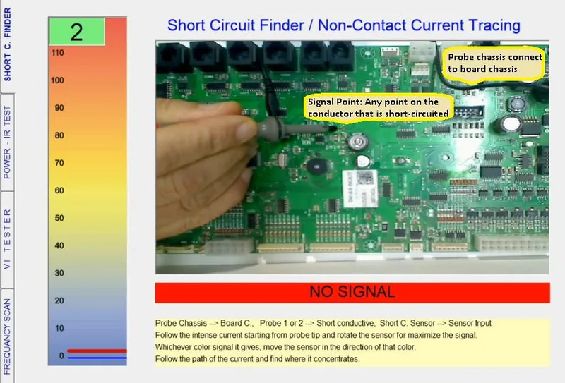
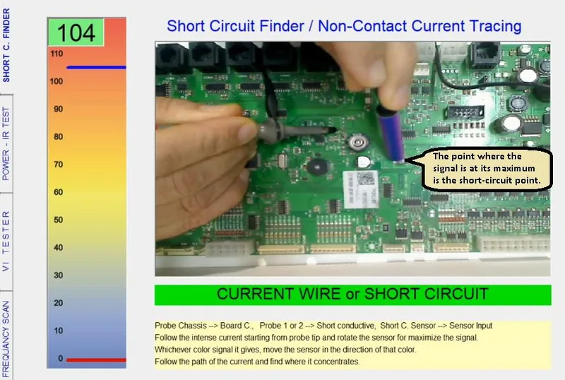
This is what closes the location gap. Nothing is cut, nothing is desoldered and no thermal camera is required: the probe injects a signal into the shorted conductor, current flows along the shorted path, and the sensor follows it to the actual point. The technician is led to the fault instead of narrowing down to it by elimination.
Step-by-Step Frequency Scanning: 3D VI Curve Analysis
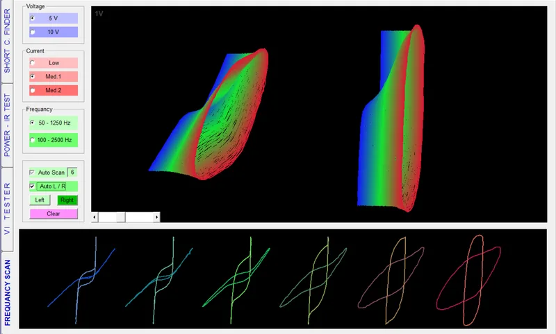
The frequency scan feature shows how components at a test point respond to frequency changes. The FADOS XI does not test at one frequency: it scans step by step, from 50 Hz to 1,250 Hz on Range 1 and from 100 Hz to 2,500 Hz on Range 2, capturing a VI curve at every single step. The software then stacks all of those curves together and builds a 3D visualisation showing how the component behaves across the entire frequency range, revealing capacitors, inductors, and frequency-dependent faults that a single-frequency VI test would miss.
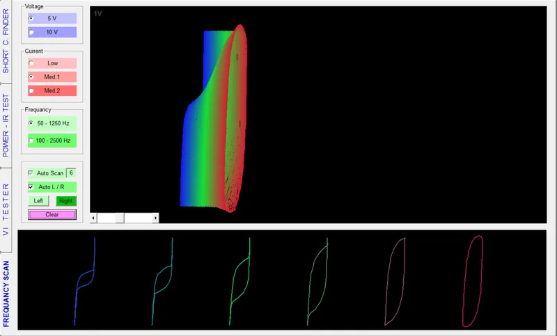
Reading the result is a shape judgement rather than a number comparison, which is what makes it fast. A healthy component gives a smooth, consistent 3D shape. A failing one shows distortion, collapsed curves, or sudden spikes at certain frequencies, clearly visible on screen and hard to miss.
Changes in the 3D shape are most visible at points where capacitors are present, the elliptical VI curve expands, rotates, and distorts as frequency sweeps through the capacitor’s impedance curve. This helps technicians:
- Determine the effective capacitance at a test point
- Identify dried-out or degraded electrolytic capacitors that behave differently at frequency
- Distinguish capacitive from inductive behaviour on complex nodes
- Verify that replacement components match the original’s frequency response
Dual-Channel VI Curve Tracing and Comparison
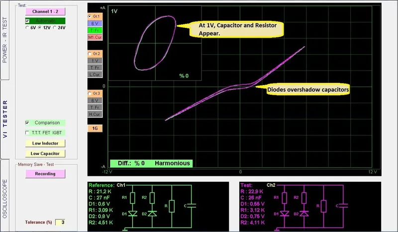
Both the FADOS 9F1 and FADOS XI support dual-channel simultaneous testing: Channel 1 (reference / known-good board) and Channel 2 (test / suspected-faulty board) are displayed side by side. Any difference in the VI curves between the two channels immediately indicates a fault at that test point.
The software calculates a percentage difference between the two channels and classifies each test point as:
- Harmonious (0% difference, perfect match)
- Attention (small discrepancy, marginal component)
- Disharmony (significant difference, fault confirmed)
Audio feedback reinforces the visual: matching points produce one sound, non-matching points produce a different sound, so the technician can focus on probing speed without watching the screen.
Equivalent Circuit Diagram and Automatic Component Measurement
One of the features unique to FADOS is the automatic equivalent circuit diagram: at every test point, the software generates a schematic showing the equivalent circuit (resistor, capacitor, inductor, diode networks) with measured values displayed alongside the diagram. This means the technician doesn’t need to calculate anything from the raw VI curve, the resistance (R), capacitance (C), inductance (L), and diode forward voltage (D) are read directly from the screen.
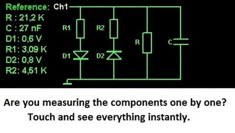
This is a fundamental advantage over a standard multimeter: a multimeter will not correctly read the capacitance of a capacitor that has a parallel resistor path (the parasitic leakage defeats the measurement). FADOS shows both the capacitor value AND the parallel resistance in the equivalent circuit, giving the technician the complete picture.
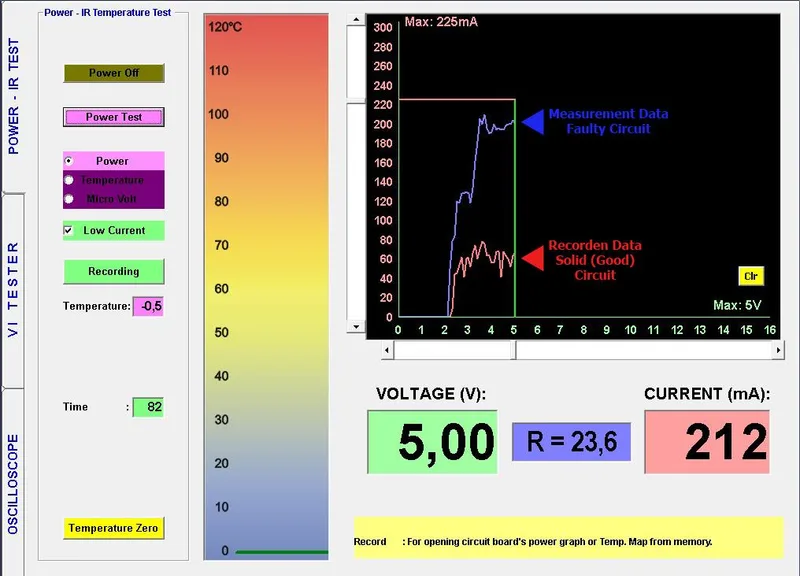
Power Supply and IR Temperature Test
The FADOS XI includes an adjustable DC power supply that energises the board under test and generates a real-time DC V-I graph: the technician can see how much current the board draws at each voltage step. A faulty board that draws excessive current compared to the reference immediately shows on the graph.
The non-contact IR temperature sensor measures the surface temperature of individual components while the board is powered. A component drawing excessive current heats up, the IR sensor locates it before the technician even touches the board with the VI probe.
FADOS 9F1 vs FADOS XI Advanced: Feature Comparison
| Feature | FADOS 9F1 | FADOS XI Advanced |
|---|---|---|
| Dual Channel VI Test | ✓ | ✓ |
| Power Output – IR Temperature Test | ✓ | ✓ |
| Automatic Equivalent Circuit Diagram | ✓ | ✓ |
| Multi-component Measurement (R/C/L/D) | ✓ | ✓ |
| Comparison from Memory | ✓ | ✓ |
| Automatic Voltage, Current, and Frequency selection | ✓ | ✓ |
| Oscilloscope, Square Wave, Analog Outputs | ✓ | ✓ |
| Automatic 1V VI display | ✓ | ✓ |
| Fault Reporting in Excel and JPG | ✓ | ✓ |
| Non-contact Short Circuit Detection Sensor | - | ✓ |
| 100–2500 Hz Frequency Scan (3D) | - | ✓ |
FADOS XI Specification
| Specification | FADOS XI |
|---|---|
| Step of voltages | ±1 V, ±3 V, ±6 V, ±12 V, ±24 V |
| Step of resistances | Low 47 kΩ, Med1 3.5 kΩ, Med2 700 Ω, High 250 Ω |
| Step of frequencies for ±6 V | Very Low 2.16 Hz, Low2 6.85 Hz, Low1 20.56 Hz, Test 54.82 Hz, High at ±1 V (Low Inductor) 7.81 kHz, High at ±3 V (Low Capacitor) 2.23 kHz |
| Number of channels | 2 channels: Channel 1, Channel 2 |
| Scan modes | Manual or automatic selection steps of voltage, current and frequency |
| Memory function | Yes, recording data with image, and fault detection by comparison with stored signatures |
| Equivalent circuit diagram | Yes |
| Resistor, capacitor, diode measurement | Yes |
| Graphs | 3 graphs at different adjustments can be screened simultaneously |
| Report saving / analytics | Yes |
| Variable DC power supply | 100 mV to 16 V at 10 mA to 1500 mA |
| Non-touched IR temperature | Monitoring temperature up to approximately 120 °C above ambient |
| Short circuit finder + frequency scanning | Yes (FADOS XI only) |
| Frequency scanning range | 50 Hz to 1,250 Hz (Range 1), 100 Hz to 2,500 Hz (Range 2) |
| Multiplexer channels | No (FADOS MUX only) |
| Oscilloscope | Sampling rate 400 K/S, ADC 2 channel 12 bit, sensitivity 2.5 mV, image rate 0.02 mS/div to 100 mS/div, instant memory 64 Kbyte, input voltage probe 1X ±5 V and 10X ±50 V |
| Square wave generator | 0.2 to 25 kHz |
| Analog output signal | -12 V to +12 V |
| Dimensions | 125 mm L x 113 mm W x 40 mm H |
| Gross weight | 1500 grams approx. |
Specifications are per the ProT Ar-Ge and GSAS FADOS booklet (PDF), August 2026, and are subject to change without prior notice.
Usage Areas
The FADOS XI is used across every industry where populated circuit boards need to be diagnosed and repaired:
- Automotive: ECU repair, body control modules, infotainment boards, instrument clusters
- Industrial: servo and stepper motor driver boards, PLC I/O modules, inverter control boards
- Medical: patient monitor boards, imaging system controllers, infusion pump electronics
- Defence and aerospace: legacy avionics repair, radar system PCBs, communication equipment
- Consumer electronics: laptop and desktop motherboards, television and display driver boards
- Textile and production machinery: machine controller electronics, sensor interface boards
Buy FADOS XI Advanced VI Analyzer in India
GSAS Micro Systems is an authorized ProT Ar-Ge engineering partner for India, supplying the full FADOS product family, FADOS 9F1, FADOS XI Advanced, and FADOS MUX multiplexer, with INR invoicing under GST, local stock, application training, and on-site commissioning support. Whether you run a PCB repair depot, a warranty return centre, an industrial maintenance workshop, or a defence electronics overhaul facility, the FADOS XI gives your technicians the fastest path from symptom to fault location on any populated circuit board without schematics, without test fixtures, and without powering up.
Contact our applications team in Bengaluru, Chennai, Hyderabad, Delhi NCR, Mumbai, or Pune for a hands-on demo.
Blog
ProT Ar-Ge Insights

FADOS Test Reports and GSAS Agent: Turning Board Test Results into an Auditable Record
A pass or fail on the FADOS screen is not a record. This guide covers what the FADOS test report contains, what GSAS Agent does with it, and how offline, Google Drive and LAN modes put a QR-linked report on the job card for repair shops and EMS lines in India.

FADOS Circuit Board Tester: Complete Guide for Indian Repair Teams
The complete guide to FADOS circuit board testers for Indian repair teams, FADOS9F1 and FADOS XI Advanced compared, VI curve tracing workflow, equivalent circuit diagrams, short circuit detection, frequency scanning, and the buying path in India.
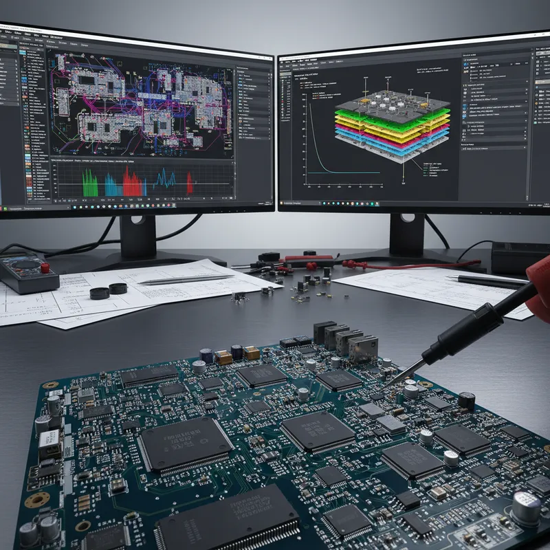
FADOS XI Frequency Scanning and VI Curve Tracing for PCB Diagnostics
A complete guide to VI curve tracing and the FADOS XI's 3D frequency scanning feature for PCB fault diagnosis, how to read VI curves, the equivalent circuit diagram, capacitor quality testing, and the dual-channel comparison workflow.
Related products
More from ProT Ar-Ge
All ProT Ar-Ge products →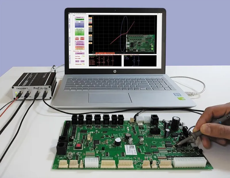
FADOS 9F1 Circuit Board Tester
Flagship VI curve tracer with built-in PSU (100mV–16V, 10mA–1.5A), IR thermal sensor, 12-bit ADC/DAC, and FADOS software for non-powered PCB diagnostics. Buy in India from GSAS.
View FADOS 9F1 Circuit Board Tester →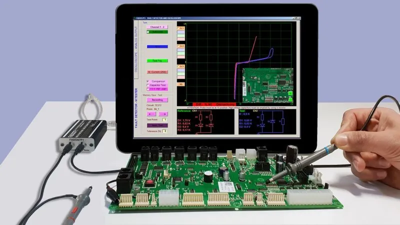
FADOS 7F1 Circuit Board Tester
Portable VI curve tracer for field service and depot repair, same FADOS analysis software as the 9F1 but in a compact form factor without internal power supply. Buy in India from GSAS.
View FADOS 7F1 Circuit Board Tester →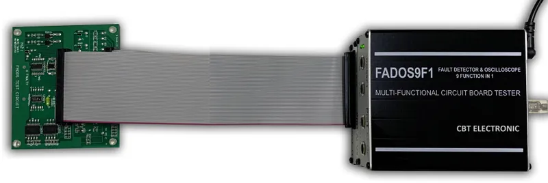
FADOS MUX Multiplexer Module
100-channel multiplexer module for FADOS 9F1, cascadable to 200 channels, for automated multi-point V-I testing through a test-point connector or a bed-of-nails fixture. Supplied and supported across India by GSAS.
View FADOS MUX Multiplexer Module →Available across India
Interested in FADOS XI Advanced VI Analyzer?
Get pricing, an evaluation unit, or a technical consultation from our application engineers.