
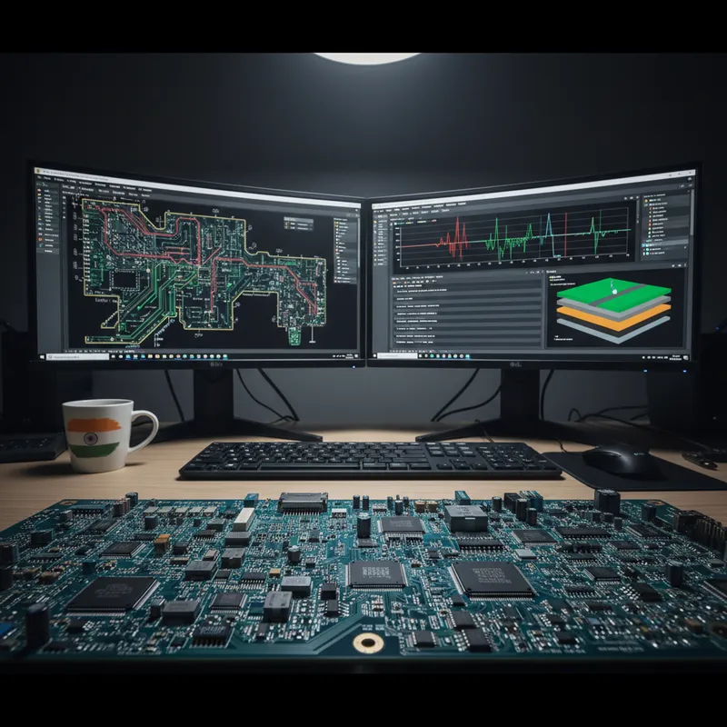
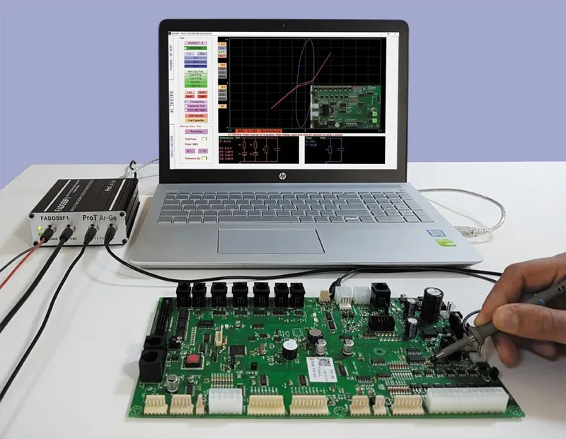
If you repair, refurbish, or quality-test populated circuit boards in India, the FADOS family from ProT Ar-Ge is the tool that changes your diagnostic workflow from guesswork to systematic fault detection. FADOS, short for FAult Detector OScilloscope, is a multi-functional circuit board diagnostic system that combines VI curve tracing, oscilloscope, adjustable DC power supply, non-contact IR temperature sensor, automatic equivalent circuit diagram generation, and component value measurement into one portable device. It diagnoses faults on populated PCBs without requiring schematics, test fixtures, or powering the board.
The current product family includes the FADOS 9F1, the FADOS XI Advanced (with short circuit detection and frequency scanning), and the FADOS MUX (100-Channel automated testing). This guide covers what FADOS does, how it works, which model to choose, and how to buy it in India.
What Is FADOS and Why Is It Different from Other PCB Testers?
FADOS is a multi-functional circuit board diagnostic system designed by ProT Ar-Ge for one purpose: finding faults on populated PCBs without schematics, without custom test fixtures, and without applying operating power to the board.
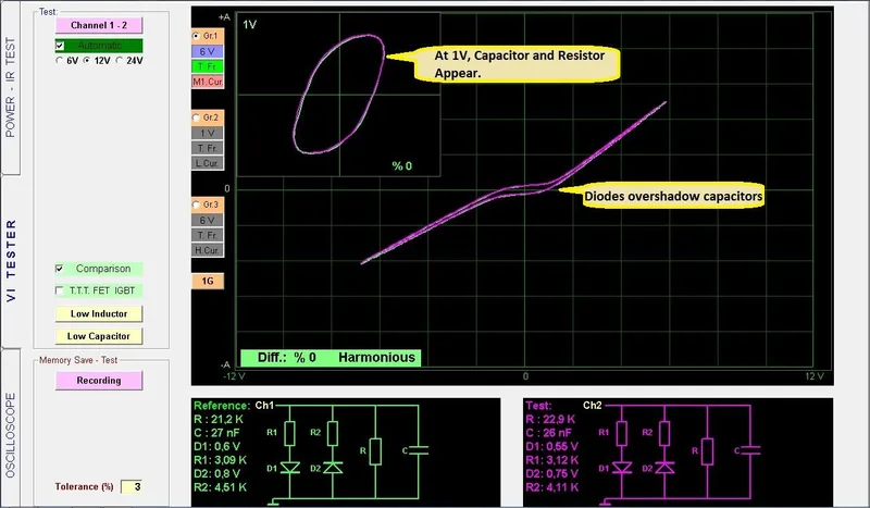
The core diagnostic method is VI (Voltage-Current) curve tracing. FADOS applies a controlled AC signal to test points on a powered-off board and plots the resulting voltage-current relationship. This VI curve is a “fingerprint” of the equivalent impedance at that node, the combined effect of every component connected to it. By comparing the VI curve from a known-good reference board against the board under test, the technician instantly sees any difference. No interpretation of schematics is needed. The comparison is visual and immediate.
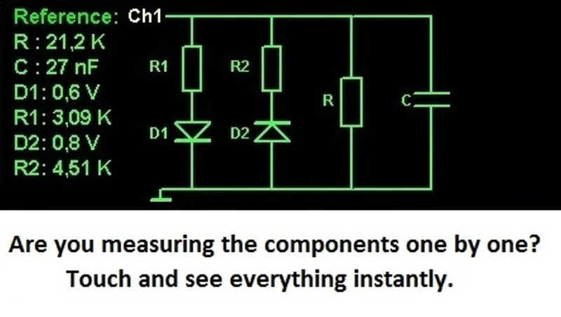
What sets FADOS apart from a basic VI curve tracer is everything it does beyond the curve itself: it auto-generates the equivalent circuit diagram (showing the R, C, L, and D values at the test point), it measures and displays those component values numerically, it overlays board photographs with marked test points, it generates Excel and JPG fault reports, and it provides audio feedback so the technician can probe rapidly without watching the screen.
Why Do Repair Technicians Need a VI Curve Tester Instead of a Multimeter?
A digital multimeter measures one parameter at a time, resistance, capacitance, voltage, or continuity, in isolation. On a populated board, this creates three problems. First, a multimeter cannot separate parallel components, you measure the parallel combination of every path, not the individual component. Second, a multimeter captures one characteristic at a time, a capacitor might read correct capacitance but have excessive ESR, invisible without a separate measurement. Third, a multimeter has no built-in reference comparison, the technician must know the correct value from a schematic or BOM.
FADOS solves all three problems simultaneously:
| Capability | Digital Multimeter | FADOS VI Curve Tester |
|---|---|---|
| Measurement type | Single parameter (R, C, V, or continuity) | Complete VI curve showing all impedance characteristics at once |
| Parallel components | Cannot separate, reads combined parallel value | Shows equivalent circuit diagram with individual R, C, L, D values |
| Reference comparison | Manual, technician must know correct values | Automatic dual-channel comparison against known-good board |
| In-circuit accuracy | Degraded by parallel paths | Designed for in-circuit measurement on populated boards |
| Audio feedback | Continuity beep only | Pass/fail tone for every test point, probe without watching screen |
| Report generation | None | Excel and JPG reports with board photos and marked fault points |
| Schematic required | Needed to interpret readings | Not required, golden reference board is sufficient |
| Thermal detection | Separate instrument needed | Integrated non-contact IR sensor |
| Power supply | Separate instrument needed | Built-in adjustable DC supply with V-I graphing |
The fundamental difference: a multimeter asks “what is this component’s value?” while FADOS asks “is this node behaving identically to the known-good reference?” The second question catches every type of deviation, wrong values, degraded components, opens, shorts, solder defects, and parasitic failures, in a single measurement.
What Is the FADOS Product Family?
ProT Ar-Ge offers three FADOS products, each targeting a different use case.
FADOS 9F1: The Established Standard
The FADOS 9F1 is the flagship diagnostic system. It includes dual-channel VI curve tracing, automatic equivalent circuit diagrams, component value measurement (R/C/L/D), a built-in adjustable DC power supply (100 mV to 16 V, 10 mA to 1.5 A), a non-contact IR temperature sensor, oscilloscope (400 KS/s, 12-bit), square wave generator, and the full FADOS Analysis Suite with Excel/JPG reporting. The 9F1 suits repair workshops, depot maintenance centres, and failure analysis labs. Units supplied by GSAS are assembled at the GSAS Bangalore ODM facility.
FADOS XI Advanced: Short Circuit Detection and Frequency Scanning
The FADOS XI Advanced builds on the 9F1 platform with two exclusive capabilities: a non-contact short circuit detection sensor and step-by-step frequency scanning (50-2500 Hz) with 3D VI curve visualization. The short circuit sensor traces current along a shorted conductor without physical contact, leading the technician directly to the fault. The frequency scan reveals how components respond across frequencies, catching degraded capacitors and frequency-dependent faults that a single-frequency VI test would miss. All 9F1 features are also present in the XI.
FADOS MUX: Automated Multi-Point Testing
The FADOS MUX is a 100-Channel multiplexer that connects to the FADOS 9F1 and enables automated sequential testing of up to 100 test points. Once a reference board is profiled, operators place each board on a pogo-pin fixture and run the automated scan, the software sequences through all points, compares each VI curve against the reference, flags deviations, and generates batch pass/fail reports. The MUX brings FADOS into the production environment: incoming inspection, end-of-line testing, and warranty return screening. For a detailed guide to deploying the MUX, see FADOS MUX in Production, Setting Up 100-Channel Automated Board Testing.
What Are All the Features of the FADOS Platform?
Both the FADOS 9F1 and FADOS XI Advanced share a comprehensive feature set. The following is the complete capability list.
VI Curve Tracing and Comparison
- Dual-channel VI curve tracing, Channel 1 (reference) and Channel 2 (test board) displayed simultaneously
- Stored signature comparison from internal memory, test against a saved reference without having the physical reference board present
- Automatic voltage, current, and frequency selection, the software selects optimal test parameters for each measurement
- 1V automatic VI display for consistent low-voltage comparison
- Percentage-based difference scoring, Harmonious, Attention, or Disharmony classification for each test point
- Audio pass/fail feedback, distinct tones for matching and non-matching points, enabling rapid probing without watching the screen
- 3G display, three voltage/frequency/current settings shown simultaneously on a single screen
Equivalent Circuit and Component Measurement
- Automatic equivalent circuit diagram, auto-generated schematic showing R, C, L, and D (diode) networks with measured values at the probe point
- Multi-component value display, resistance, capacitance, inductance, and diode forward voltage read directly from the screen
Power Supply and Thermal Testing
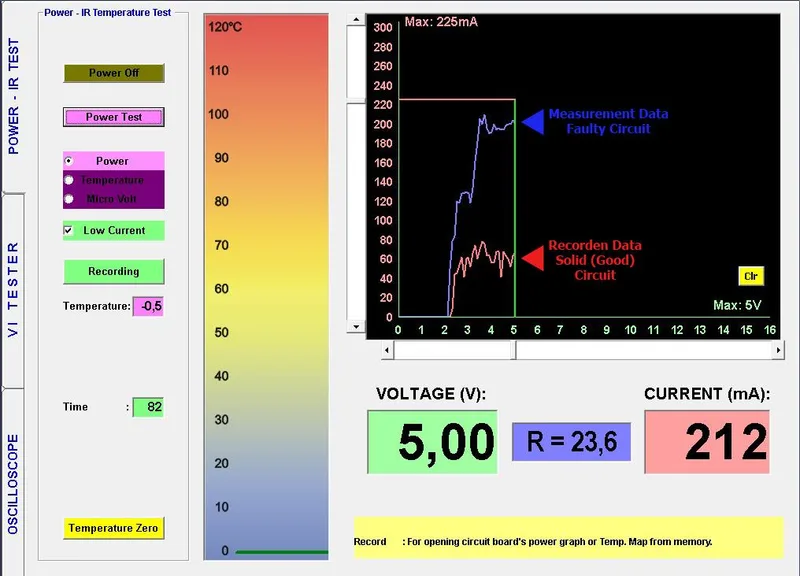
- Adjustable DC power supply, energize the board under test and generate a real-time DC V-I graph showing current draw versus voltage
- Non-contact IR temperature sensor, detect overheating components on powered boards before probing
Oscilloscope and Signal Generation
- Built-in oscilloscope, 400 KS/s, 2 channels, 12-bit ADC, 2.5 mV sensitivity, 64 KB memory
- Square wave generator, 0.2 to 25 kHz
- Analog voltage output, -12 V to +12 V
Documentation and Reporting
- Board photo overlay with numbered test point markers, photograph the board, then annotate each probed location on the image
- Excel and JPG fault reporting, generate documentation for quality records and customer communication
- Measurement archiving and historical trend analysis
FADOS XI Exclusive Features
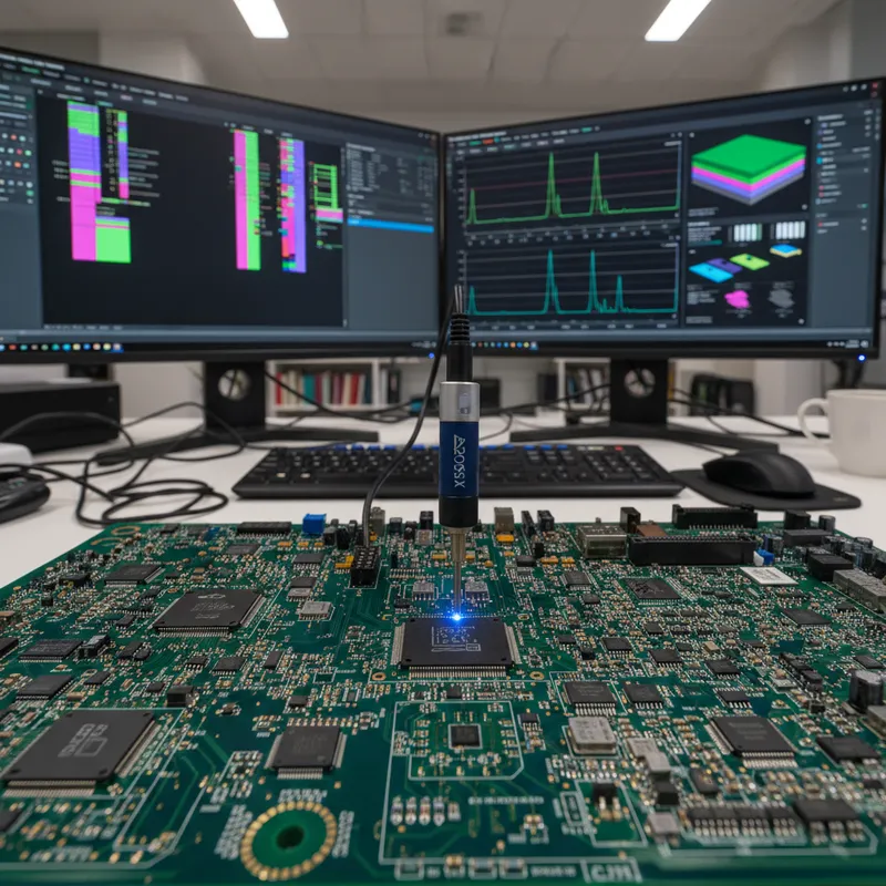
- Non-contact short circuit detection sensor: directional current sensor that follows the current path to the exact short-circuit location, with colour-coded direction indication
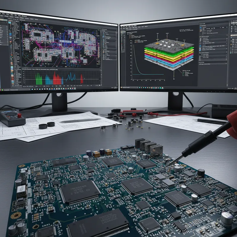
- Step-by-step frequency scanning (50-2500 Hz): sweeps through frequencies in controlled steps, building a 3D visualization of VI curve evolution to reveal capacitors, inductors, and frequency-dependent faults
Which FADOS Model Should You Buy: FADOS 9F1 or FADOS XI Advanced?
The choice depends on the types of faults you encounter most frequently and whether your boards suffer from short circuits that are difficult to locate.
| Feature | FADOS 9F1 | FADOS XI Advanced |
|---|---|---|
| Dual-channel VI curve tracing | Yes | Yes |
| Stored signature comparison from memory | Yes | Yes |
| Automatic equivalent circuit diagram | Yes | Yes |
| Multi-component measurement (R/C/L/D) | Yes | Yes |
| Adjustable DC power supply + V-I graph | Yes | Yes |
| Non-contact IR temperature sensor | Yes | Yes |
| Oscilloscope, square wave, analog output | Yes | Yes |
| Automatic voltage/current/frequency selection | Yes | Yes |
| 1V automatic VI display | Yes | Yes |
| 3G display (3 settings simultaneously) | Yes | Yes |
| Audio pass/fail feedback | Yes | Yes |
| Excel/JPG fault reporting | Yes | Yes |
| Board photo overlay with test points | Yes | Yes |
| FADOS MUX compatibility | Yes | - |
| Non-contact short circuit detection sensor | No | Yes |
| Frequency scanning 50-2500 Hz (3D) | No | Yes |
Choose the FADOS 9F1 if:
- Your primary need is VI curve comparison, equivalent circuit diagnostics, power/IR testing, and fault documentation
- Short circuit tracing is infrequent or handled by other methods in your workshop
- You plan to add the FADOS MUX for automated production testing
- You need the proven, established platform with an installed base of reference board databases
Choose the FADOS XI Advanced if:
- Short circuit faults are a recurring problem in your repair work, the non-contact sensor eliminates the manual hunt for shorts
- You work with boards containing many capacitors where frequency-dependent degradation is a concern (power supply boards, motor driver boards, inverter controls)
- You want the most capable single instrument for comprehensive diagnostics
Both models share the same FADOS Analysis Suite software. Reference databases are compatible, so teams that deploy both can share golden board data across instruments. For a comparison against the more compact FADOS 7F1 (portable, without power supply or IR sensor), see FADOS 9F1 vs 7F1, Which Circuit Board Tester Is Right for Your Workshop?.
How Do You Use FADOS to Find a Fault on a Circuit Board?
The FADOS diagnostic workflow is systematic and repeatable. A technician who has never seen a particular board before can diagnose it using only a known-good reference, no schematics, no BOM, no prior experience with that design.
Step 1, Connect the reference board. Attach the Channel 1 probe to a known-good (golden) board. This board represents the correct behaviour at every test point.
Step 2, Record signatures to memory. Probe each test point on the reference board and save the VI curve signature to the FADOS database. Photograph the board and mark each point’s location on the image. This reference library is saved permanently and can be reused for every future board of the same design.
Step 3, Connect the suspect board. Attach the Channel 2 probe to the board under test (the board with the reported fault). The board is not powered, all testing is performed with the board switched off.
Step 4, Probe matching test points. Touch the same points on the suspect board that were recorded from the reference. FADOS displays the Channel 1 (reference) and Channel 2 (test) VI curves side by side, calculates the percentage difference, and gives an audio tone: a matching tone for identical curves, a different tone for deviations. The technician can probe rapidly, moving point to point, guided by sound alone.
Step 5, Inspect flagged points. Any point where the software flags a deviation (classified as Attention or Disharmony) is a candidate fault location. At each flagged point, the technician examines the equivalent circuit diagram and component values to understand what has changed, a resistor gone open, a capacitor shorted, a diode degraded, or a wrong-value component installed.
For a deeper dive into the VI curve tracing technique itself, see VI Curve Tracing Explained, How FADOS Finds PCB Faults Without Power. For guidance on interpreting individual component signatures, see VI Curve Signature Analysis, Reading Component Fingerprints on Unpowered Boards.
What Kinds of Faults Does FADOS Detect?
FADOS detects any fault that changes the impedance characteristics at a test point. Because the VI curve captures the aggregate electrical behaviour of every component connected to that node, the range of detectable faults is broad:
- Open circuits: broken traces, cracked solder joints, lifted pads, broken vias. The VI curve shows a dramatically different shape when a component or trace path is missing.
- Short circuits: solder bridges, conductive contamination, failed components creating unintended connections. The VI curve collapses toward a resistive straight line.
- Wrong-value components: incorrect resistor, capacitor, or inductor installed during assembly. The equivalent circuit diagram shows the measured value, which the technician can compare to the expected value.
- Degraded capacitors: dried-out electrolytic capacitors with increased ESR, leaky ceramic capacitors, capacitors with reduced capacitance. The VI curve ellipse changes shape and the equivalent circuit shows the degraded values. For a specific repair guide on this fault type, see Finding Shorted Decoupling Capacitors with VI Curve Tracing.
- Failed diodes and transistors: open, shorted, or leaky semiconductor junctions show as distorted VI curve shapes in the diode quadrants.
- Shorted ICs: internal die failures that short supply pins to ground, or ESD damage that creates parasitic paths.
- ESD damage: electrostatic discharge damage to sensitive inputs that may not be visible under magnification but changes the impedance signature.
- Solder and BGA defects: cold joints, insufficient solder, head-in-pillow defects, open balls, bridged pins, and fractured interconnects under BGA packages. For BGA-specific guidance, see Detecting BGA Solder Joint Failures with VI Curve Analysis.
The FADOS XI’s non-contact short circuit sensor adds a further capability: it traces the physical path of a short circuit on the board, leading the technician directly to the fault location.
Which Industries Use FADOS in India?
FADOS is deployed wherever populated circuit boards need to be diagnosed and repaired. The following industries represent the primary user base in India.
Automotive ECU Repair. Aftermarket repair centres and OEM warranty return facilities use FADOS to diagnose ECUs, body control modules, instrument clusters, and infotainment boards. Board-level repair is increasingly preferred over complete module replacement, and FADOS enables technicians to locate faults without the vehicle manufacturer’s schematics.
Industrial Maintenance. Manufacturing plants use FADOS to diagnose PLC boards, servo drive controllers, VFDs, CNC controllers, and process instruments on-site, reducing dependence on expensive OEM spares and eliminating weeks-long turnaround for manufacturer repair. Industrial estates in Pune, Chennai, Bengaluru, and Delhi NCR are significant deployment areas.
Medical Device Service. Hospitals and third-party service organizations use FADOS to repair patient monitor boards, ultrasound controllers, ventilator electronics, and infusion pump circuits, extending the service life of imported equipment rather than replacing at import prices.
Defence Electronics Depot Repair. Depot technicians repair avionics, radar, and communication boards where schematics may be restricted. FADOS’s reference-comparison methodology lets them diagnose without access to classified design documentation.
Consumer Electronics Repair. Laptop motherboard shops, television service centres, and mobile board repair technicians use FADOS for systematic fault detection, a significant diagnostic advantage over manual multimeter probing in India’s repair-oriented market.
Textile and Production Machinery. Loom controllers, knitting machine boards, and embroidery machine electronics across Gujarat, Tamil Nadu, and Maharashtra are diagnosed with FADOS when controller boards fail.
For a detailed look at industry applications, see 5 Industries Where FADOS Board Testers Are Transforming PCB Repair in India.
How Does FADOS Compare to In-Circuit Testing (ICT)?
FADOS and ICT (In-Circuit Testing) serve different operational contexts and are often complementary rather than competing.
| Criterion | FADOS VI Curve Tracing | In-Circuit Testing (ICT) |
|---|---|---|
| Equipment cost | Accessible to small and mid-size operations | High capital investment (Rs 50 lakh and above) |
| Test fixture | No fixture needed for manual probing; simple pogo fixture for MUX | Custom bed-of-nails fixture required (Rs 5-20 lakh per board design) |
| Fixture lead time | Immediate (manual) or 1-2 weeks (MUX) | 4-8 weeks |
| Schematic required | No, golden reference board is sufficient | Yes, for fixture design and test program development |
| Measurement type | Node-level impedance signature comparison | Individual component value measurement |
| Repair diagnostics | Strong, localizes specific fault with equivalent circuit | Limited, identifies failed node but not root cause |
| Legacy board support | Works with any board, any age, any manufacturer | Requires design data, netlist, and BOM |
| Production throughput | 30-90 seconds per board with MUX | 5-15 seconds per board |
| Best for | Repair, depot maintenance, low-mid volume, mixed board types | High-volume production testing (over 10,000 per year of same design) |
FADOS wins when: you repair boards from multiple designs, work without schematics, need fault localization (not just pass/fail), or support legacy boards. ICT wins when: you produce high volumes of a single design and need component-level measurement at production speed. Many operations use both: ICT for production screening, FADOS for failure analysis on boards that ICT rejects.
For a full comparison, see FADOS VI Curve Tracer vs ICT, Which PCB Test Strategy Fits Your Operation?.
How Do You Test a Circuit Board Without a Schematic?
You need one working example of the same board, a “golden reference.” Probe every accessible test point on the reference and save the VI curve signatures to the FADOS database. When a faulty board arrives, probe the same points, FADOS auto-compares each signature against the stored reference, flags deviations with audio and visual indicators, and displays the equivalent circuit diagram at every flagged point so the technician can identify the specific fault.
No schematic is consulted. No BOM is needed. No design files are required. This makes FADOS the primary diagnostic tool for depot-level repair of legacy equipment, third-party repair of proprietary boards, and any operation where design documentation is unavailable or restricted.
For the full methodology, see Complete Guide to VI Curve Tracing for PCB Repair.
Where Can You Buy FADOS in India?
GSAS Micro Systems is an authorized ProT Ar-Ge engineering partner for India, providing the complete FADOS product family, FADOS 9F1, FADOS XI Advanced, FADOS 7F1, and FADOS MUX, with INR invoicing under GST, local inventory, application training, and on-site commissioning support.
FADOS 9F1 units are assembled at the GSAS Bangalore ODM facility. GSAS provides:
- Pre-sales consultation: application engineers evaluate your board types, fault profiles, and throughput requirements to recommend the right FADOS configuration
- On-site installation and training: hands-on training with your actual boards, including reference board profiling and database creation
- Ongoing technical support: software updates, calibration services, and remote application support
- Demo units: hands-on evaluation before purchase at any GSAS office
- INR invoicing: GST-compliant documentation for all procurement channels
Visit the ProT Ar-Ge partner page for the full product portfolio and application resources.
Further Reading
GSAS internal resources:
- FADOS 9F1 product page, specifications, datasheet, and store link
- FADOS XI Advanced product page, specifications and feature details
- FADOS MUX product page, 100-Channel automated testing module
- ProT Ar-Ge partner page, company overview and full product portfolio
- VI Curve Tracing Explained, How FADOS Finds PCB Faults Without Power
- FADOS VI Curve Tracer vs ICT, Which PCB Test Strategy Fits Your Operation?
- FADOS 9F1 Advanced Features, Powered Board Testing and IR Thermal Scanning
- PCB Repair Guide, Diagnosing Voltage Regulator Failures with FADOS
External references:
- ProT Ar-Ge official website, manufacturer product pages and documentation
- VI Curve Testing, Wikipedia, background on curve tracing methodology
GSAS Micro Systems is an authorized ProT Ar-Ge engineering partner for India, with offices in Bengaluru, Hyderabad, Chennai, Pune, Mumbai, and Delhi NCR. Whether you operate a PCB repair depot, an automotive ECU service centre, an industrial maintenance workshop, or a defence electronics overhaul facility, our applications team can help you select the right FADOS configuration and get your team productive from day one. Contact us to schedule a live demonstration with your boards.
Also appears in:
Interested in ProT Ar-Ge tools?
Talk to our application engineers for personalized tool recommendations.
More from ProT Ar-Ge
View all →
FADOS Test Reports and GSAS Agent: Turning Board Test Results into an Auditable Record
4 Aug · 8 min
FADOS XI Frequency Scanning and VI Curve Tracing for PCB Diagnostics
16 Apr · 11 min
FADOS XI Non-Contact Short Circuit Detection: Find PCB Shorts in Seconds
16 Apr · 9 min

The Economics of Board-Level Repair in India: Why More Workshops Are Investing in Diagnostics
5 Apr · 7 min

Emulating Processor Power for Thermal Testing: Why Constant Power
7 Oct · 7 min

CRPS and Rack Power Supply Testing: The Six Tests That Matter
7 Oct · 7 min