
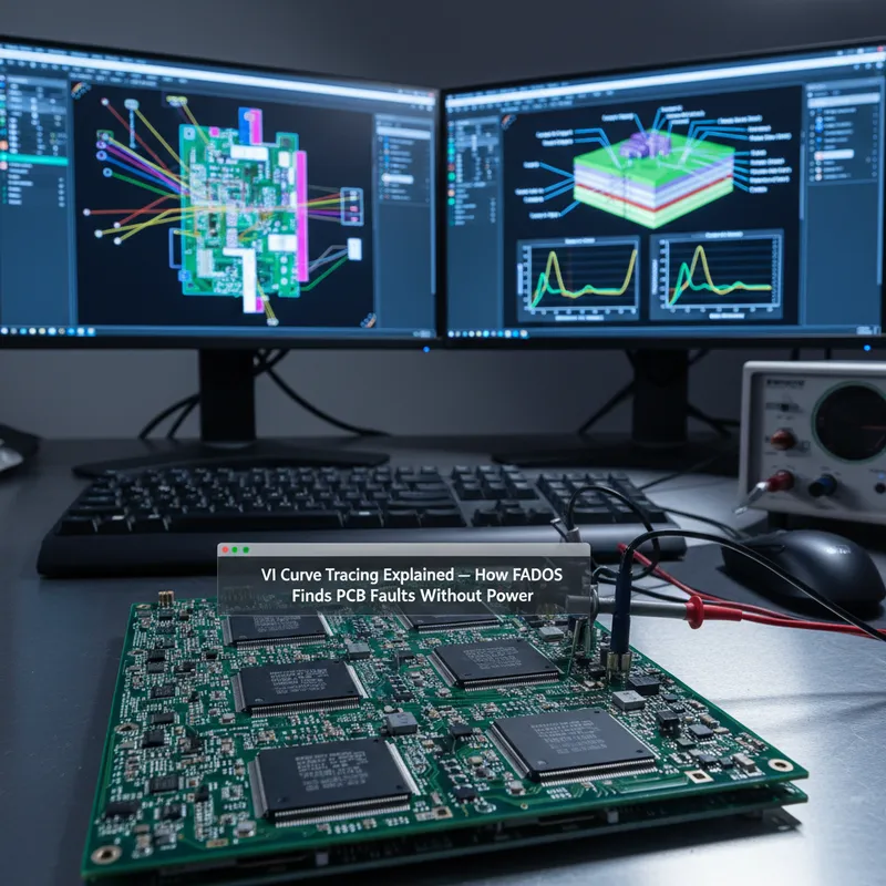
What Is VI Curve Tracing?
VI curve tracing (also called signature analysis) is a power-off test method that identifies faults on populated circuit boards by comparing the voltage-current (V-I) characteristic of each component or node against a known-good reference. Unlike traditional troubleshooting methods that require schematics, powered test fixtures, or functional knowledge of the circuit, VI curve tracing works on any board, powered off, no schematic needed.
The principle is simple: apply a controlled, current-limited AC test signal to a point on the board and measure the resulting V-I curve. Every component, resistor, capacitor, diode, transistor, IC, produces a distinctive V-I signature. Compare the signature from a working board against a suspect board, and deviations immediately reveal the fault location and type.
How FADOS Implements VI Curve Tracing
FADOS (Fault Detector and Oscilloscope) from ProT Ar-Ge implements VI curve tracing with a dual-channel architecture. One channel connects to a known-good reference board, the other to the board under test. The FADOS software overlays both V-I curves in real time, any difference between the two curves indicates a fault.
The key advantages over manual multimeter probing:
- Speed: probe a point and instantly see if it matches the reference. No need to look up expected values.
- No schematic required: you only need one working board as a reference. FADOS stores reference signatures in a database for future comparisons even without the reference board present.
- Component-level resolution: the V-I curve shape reveals the component type and condition. A shorted capacitor, a leaky transistor, a wrong-value resistor, each produces a distinctly different curve deviation.
- Safe: testing is done with the board powered off. No risk of further damage to already-faulty boards, no risk to the operator.
What Faults Can VI Curve Tracing Detect?
| Fault Type | V-I Curve Indicator |
|---|---|
| Short circuit | Curve collapses to a straight line (pure resistive) |
| Open circuit | Curve flattens to horizontal (no current flow) |
| Wrong-value resistor | Curve slope changes (steeper = lower resistance) |
| Leaky capacitor | Elliptical curve shifts or distorts |
| Failed semiconductor | Curve loses characteristic diode knee |
| Degraded component | Subtle curve shape change vs. reference |
| Solder joint failure | Intermittent or shifted curve |
FADOS 9F1: Beyond Basic VI Tracing
The FADOS 9F1 adds two capabilities beyond power-off signature analysis:
1. Built-in programmable power supply (100 mV to 16 V, 10 mA to 1.5 A): apply DC power to the board and observe current draw. Faulty components that draw excessive current under power are immediately visible in the V-I characteristics, complementing the power-off signature analysis.
2. Non-contact IR temperature sensor: after briefly powering the board, use the IR sensor to detect components that are overheating due to fault-related excessive current draw. Combined with the power supply, this technique reaches fault classes that power-off testing alone cannot isolate.
Industries Using FADOS in India
GSAS provides FADOS systems to repair centres and production facilities across multiple industries:
- Automotive: ECU repair, powertrain control module diagnostics
- Aerospace & Defence: avionics board repair, radar system maintenance
- Industrial Automation: PLC and drive repair, motor controller diagnostics
- Medical Devices: service depot repair of diagnostic equipment
- Consumer Electronics: high-volume board repair operations
- Telecom: base station and networking equipment maintenance
Getting Started with FADOS
GSAS Micro Systems is an authorized ProT Ar-Ge partner, providing FADOS sales, training, and support from 11 offices across India. All FADOS units are assembled and tested at our Bangalore facility.
Also appears in:
Interested in ProT Ar-Ge tools?
Talk to our application engineers for personalized tool recommendations.
More from ProT Ar-Ge
View all →
FADOS Test Reports and GSAS Agent: Turning Board Test Results into an Auditable Record
4 Aug · 8 min

FADOS Circuit Board Tester: Complete Guide for Indian Repair Teams
16 Apr · 13 min
FADOS XI Frequency Scanning and VI Curve Tracing for PCB Diagnostics
16 Apr · 11 min
FADOS XI Non-Contact Short Circuit Detection: Find PCB Shorts in Seconds
16 Apr · 9 min

Emulating Processor Power for Thermal Testing: Why Constant Power
7 Oct · 7 min

CRPS and Rack Power Supply Testing: The Six Tests That Matter
7 Oct · 7 min


