
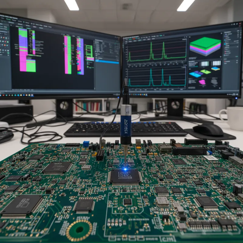
Short circuits on populated PCBs are among the most time-consuming faults to diagnose. The board is dead, the multimeter confirms near-zero resistance between power and ground, and now the technician has to find where on a dense multi-layer board that short actually is. For decades, the options were trace-cutting, thermal cameras, or brute-force component removal. The FADOS XI Advanced VI Analyzer from ProT Ar-Ge changes that equation entirely with a non-contact short circuit detection sensor that traces the current path to the exact fault point, without powering the board, without cutting traces, and without touching the conductor.
This guide explains how the technology works, how it compares to traditional methods, what types of shorts it can find, and why it matters for PCB repair operations across India.
What Is Non-Contact Short Circuit Detection?
Non-contact short circuit detection is a technique where a directional current sensor traces the path of current flowing along a short-circuited conductor without physically touching the trace or component lead. Instead of measuring resistance (which only tells you that a short exists) or heating patterns (which only show you which component is getting hot), non-contact detection follows the actual current flow through the PCB copper, via by via and trace by trace, until it reaches the point where the short-circuit connection occurs.
The FADOS XI Advanced VI Analyzer from ProT Ar-Ge is the instrument that implements this technique. FADOS stands for FAult Detector OScilloscope, a multi-functional circuit board diagnostic system that combines VI curve tracing, oscilloscope, DC power supply, IR thermal sensing, equivalent circuit diagram generation, and now, with the XI model, non-contact short circuit tracing.
The sensor itself is a directional magnetic field detector. When current flows through a conductor, it generates a magnetic field around that conductor. The FADOS XI sensor detects the direction and magnitude of that field. By moving the sensor along the surface of the PCB, the technician can follow the current from the injection point, through traces, vias, and planes, all the way to the location where the short-circuit connection completes the loop.
How Does the FADOS XI Short Circuit Sensor Work?
The workflow is straightforward and repeatable. A technician with no prior knowledge of the board layout can locate a short circuit by following these steps:
- Connect the ground clip to the board’s chassis ground or the ground plane, this establishes the return path for the test signal.
- Touch the probe tip to one side of the shorted conductor, typically the power rail that shows near-zero resistance to ground. The FADOS XI injects a low-level signal through the probe.
- Place the non-contact sensor on the PCB surface near the probe point. The sensor immediately detects the current flowing through the conductor beneath it.
- Read the colour-coded signal on the FADOS software display. The sensor produces two signals, red and blue, that indicate the direction of current flow. When the red signal is dominant (red line pointing upward), current is flowing toward the red side of the sensor. When the blue signal dominates, current flows toward the blue side.
- Follow the dominant signal direction. Move the sensor along the PCB surface in the direction indicated by the stronger colour signal. As you move closer to the short-circuit point, the signal strength increases.
- Identify the fault location. The point where the signal reaches its maximum amplitude is the exact location of the short circuit, the copper bridge, the solder splash, the failed component, or the via-to-plane connection where the unwanted path exists.
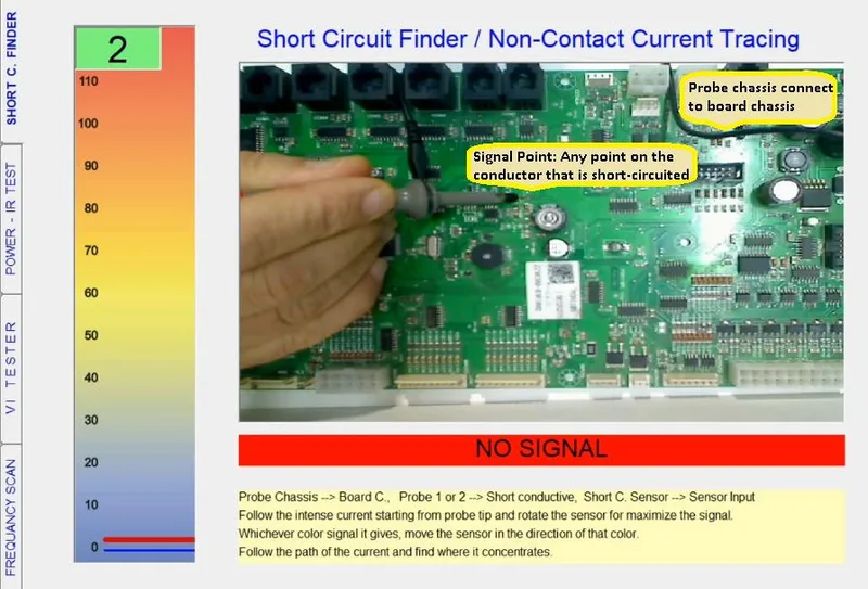
The entire process takes seconds on a single-layer or double-layer board and typically under a minute on dense multi-layer boards with buried vias. The technician does not need schematics, does not need to know the board layout, and does not need to power the board.
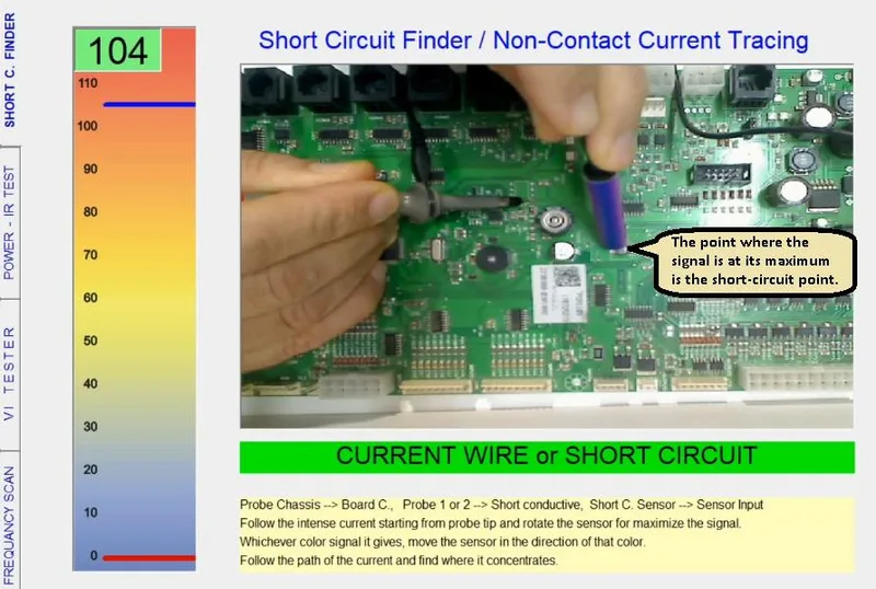
The colour-coded direction system is what makes this practical. On a complex board, current from the injection point may split into multiple paths through the copper. The sensor always shows the net direction of current at the point where it is positioned, so the technician can navigate through splits and junctions by following the strongest signal path, which is always the path to the lowest-impedance fault.
How Is This Different from Using a Multimeter to Find Shorts?
A multimeter is typically the first tool a technician reaches for when a board is suspected to have a short circuit. Setting the multimeter to resistance (ohms) mode and measuring between the power rail and ground rail quickly confirms whether a short exists, a reading of less than one ohm (or near-zero) confirms the short.
But that is where the multimeter’s usefulness ends. A multimeter tells you that a short exists. It does not tell you where on the board the short is.
To isolate the fault with a multimeter alone, the technician has to:
- Desolder components one at a time from the shorted rail, re-measuring after each removal. On a board with 50 components connected to a power rail, this can take hours.
- Cut traces to isolate sections of the board, narrowing down which segment contains the short. This is destructive and requires repair after diagnosis.
- Measure milliohm differences between multiple points on the rail, hoping to see a resistance gradient that points toward the short. On a board with wide power planes, these differences are often too small to measure reliably.
The FADOS XI eliminates all of these steps. The non-contact sensor traces the current path directly to the fault. No desoldering, no trace cutting, no guesswork. The multimeter confirms the short exists; the FADOS XI finds it.
This distinction matters enormously in production and repair environments where time is money. A technician spending two hours desoldering components to find a short that the FADOS XI would locate in seconds is not just slow, they are also risking heat damage to good components and pad-lift damage to the PCB itself.
How Is This Different from Using a Thermal Camera?
Thermal imaging cameras (FLIR, InfiRay, or similar) are another common tool for diagnosing shorts. The theory is simple: a short circuit draws excessive current, which heats up the component or trace where the short occurs. Point the thermal camera at the powered board and look for the hot spot.
This approach has three fundamental limitations:
The board must be powered. To generate a thermal signature, current must flow through the short. This means the faulty board must be energised, which risks further damage to the board, especially if the short is in a sensitive area (near a processor, near a voltage regulator, near ESD-sensitive components). Some shorts are severe enough that powering the board causes immediate secondary damage.
Thermal cameras show heat, not fault location. A hot component is not necessarily the faulty component. On a shorted power rail, the component drawing the most current gets hottest, but that might be the voltage regulator (which is doing its job, trying to supply current into the short) rather than the shorted capacitor downstream. The thermal camera shows a symptom (heat) rather than the root cause (the short-circuit connection itself).
Resolution limits on dense boards. On modern high-density boards with 0201-size components and BGA packages, the thermal resolution of affordable cameras may not distinguish between adjacent components. The thermal bloom from one hot component can mask the actual fault location.
The FADOS XI avoids all three limitations. It works without powering the board, the test signal is generated by the FADOS XI itself at a safe, low level. It traces the current path, not the thermal consequence of current. And it works at trace-level resolution because the magnetic field sensor responds to the conductor directly beneath it, regardless of component density.
There is a place for thermal cameras in PCB diagnosis, they are excellent for identifying components that are running outside their thermal envelope during normal operation, and for catching intermittent faults that only appear under load. But for finding the location of a dead short on an unpowered board, the FADOS XI non-contact sensor is the more direct tool.
What Kinds of Short Circuits Does the FADOS XI Find?
The non-contact sensor works on any short circuit that creates a low-impedance path between two conductors on the board. The most common types encountered in repair and manufacturing environments include:
- Solder bridges between adjacent traces or pads: the most common manufacturing defect, especially on fine-pitch QFP and 0402/0201 component pads. A microscopic solder splash creates a connection between a power trace and a ground trace (or between two signal traces).
- Copper bridge defects from PCB fabrication: etching defects that leave a thin copper bridge between traces that should be isolated. These are caught during ICT or functional test at the factory, but the FADOS XI pinpoints the exact location for rework.
- Internal IC latch-up or die failure: when an IC suffers ESD damage or latch-up, an internal junction may fail short, pulling a power pin to ground through the die. The FADOS XI traces current to the specific IC pin where the short enters the package.
- Via-to-plane shorts on multi-layer boards: a via intended to connect to one internal plane may have a manufacturing defect that shorts it to an adjacent plane. These are invisible from the surface and almost impossible to find without a current-tracing tool.
- Capacitor breakdown shorts: MLCC capacitors (especially in the 0402 and smaller sizes) can crack due to board flex or thermal stress, creating a short through the dielectric. This is the single most common failure mode in modern electronics.
- ESD-damaged protection diodes: TVS diodes and ESD clamp diodes that have been damaged by an ESD event may fail short, clamping a signal line or power rail to ground permanently.
In each case, the FADOS XI sensor does not care about the cause of the short, it only cares about the path of current flow. Whatever created the low-impedance connection, the sensor traces the current to it.
Where Is Non-Contact Short Circuit Detection Used in India?
Indian electronics manufacturing and repair operations face a specific set of challenges that make the FADOS XI particularly relevant:
EMS warranty return and repair centres. India’s growing EMS industry handles warranty returns for consumer electronics, automotive electronics, and industrial equipment. Boards arrive with “no power” or “dead board” symptoms, and the repair centre must diagnose the fault within the warranty SLA. The FADOS XI reduces diagnosis time from hours of probing and desoldering to seconds of sensor-guided tracing.
Defence electronics repair depots. India’s defence sector overhauls electronic systems for radar, communications, and avionics, often legacy designs where schematics are restricted and replacement boards have long lead times. The FADOS XI enables component-level repair on boards the technician has never seen before, without schematics, by comparing against a known-good reference and tracing shorts directly.
Automotive ECU repair workshops. ECU repair (engine control units, body control modules, instrument clusters) is a growing specialisation in India. ECUs often fail due to shorted capacitors or ESD-damaged protection diodes. The FADOS XI locates the fault so the workshop can replace the specific component rather than swapping the entire ECU assembly.
Laptop and mobile motherboard repair centres. Short circuits on power rails, caused by failed MOSFETs, shorted MLCCs, or liquid damage, are among the most common laptop faults. The FADOS XI traces the short directly, replacing the tedious practice of injecting voltage and following heat with a thermal camera.
Industrial automation spare-parts repair. Manufacturing plants rely on PLC modules, servo drive boards, and VFD control cards. When these fail, replacement costs are high and international OEM lead times are long. The FADOS XI equips in-house repair teams with a tool that works on any board, from any manufacturer, without proprietary test fixtures.
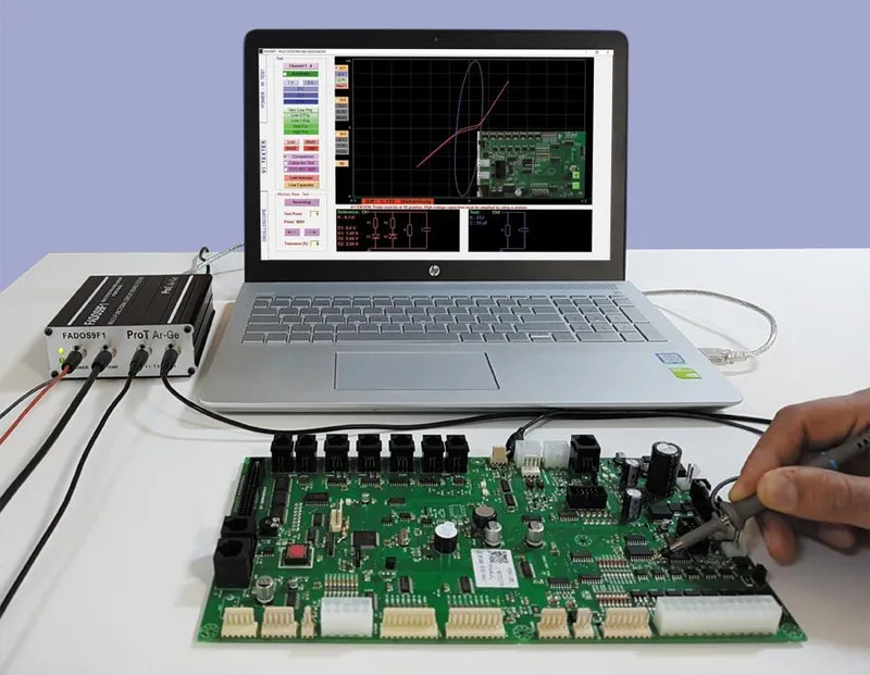
FADOS9F1 vs FADOS XI: Which One Has the Short Circuit Sensor?
Only the FADOS XI Advanced includes the non-contact short circuit detection sensor. The FADOS9F1, ProT Ar-Ge’s established VI curve tracing platform, has every other diagnostic feature (dual-channel VI, equivalent circuit, power supply, IR sensor, oscilloscope, reporting) but does not include the short circuit sensor or the 3D frequency scanning capability.
If your primary need is VI curve comparison between a known-good and a suspect board, the FADOS9F1 is a proven and capable instrument. If you frequently diagnose short circuits on dense multi-layer boards, especially boards without available schematics, the FADOS XI’s non-contact sensor is the differentiating feature that justifies the upgrade.
Here is the complete feature comparison:
| Feature | FADOS 9F1 | FADOS XI Advanced |
|---|---|---|
| Dual Channel VI Test | Yes | Yes |
| Power Output and IR Temperature Test | Yes | Yes |
| Automatic Equivalent Circuit Diagram | Yes | Yes |
| Multi-component Measurement (R/C/L/D) | Yes | Yes |
| Comparison from Memory | Yes | Yes |
| Automatic Voltage, Current, and Frequency Selection | Yes | Yes |
| Oscilloscope, Square Wave, Analog Outputs | Yes | Yes |
| Automatic 1V VI Display | Yes | Yes |
| Fault Reporting in Excel and JPG | Yes | Yes |
| Non-contact Short Circuit Detection Sensor | No | Yes |
| 100-2500 Hz Frequency Scan (3D VI Curves) | No | Yes |
Both instruments share the same software platform, USB interface, and dual-channel probe architecture. The FADOS XI adds the short circuit sensor (included as a hardware accessory) and the frequency scanning firmware module. The sensor is not a retrofit option for the 9F1, existing users will need to upgrade to the XI unit.
What Is the Fastest Way to Find a Short Circuit on a PCB?
The fastest method to locate a short circuit on a populated PCB is non-contact current tracing with a directional sensor, the technique implemented by the FADOS XI. Here is a summary comparison of the three most common approaches:
| Method | Tells You a Short Exists | Locates the Short | Board Powered? | Destructive? |
|---|---|---|---|---|
| Multimeter (resistance mode) | Yes | No, requires desoldering or trace cutting to isolate | No | Yes (if cutting traces) |
| Thermal camera | Indirectly (hot spot) | Approximate, shows heat, not fault point | Yes, risk of further damage | No |
| FADOS XI non-contact sensor | Yes (via VI curve) | Yes, traces current to exact point | No | No |
The FADOS XI combines the confirmation step (the VI curve trace confirms the short exists and shows its electrical characteristics) with the location step (the non-contact sensor traces the current to the fault). No other single instrument provides both capabilities in one workflow.
Further Reading
GSAS Micro Systems resources
- VI Curve Tracing Explained, How FADOS Finds PCB Faults Without Power, a complete guide to the VI curve tracing technique that forms the foundation of all FADOS diagnostic workflows.
- PCB Repair Guide, Finding Shorted Decoupling Capacitors with VI Curve Tracing, a practical repair walkthrough for the most common short-circuit failure mode in modern electronics.
- 5 Industries Where FADOS Board Testers Are Transforming PCB Repair in India, how automotive, defence, industrial, medical, and consumer electronics repair operations across India use FADOS testers.
- FADOS 9F1 vs 7F1, Which Circuit Board Tester Is Right for Your Workshop?, a side-by-side comparison of ProT Ar-Ge’s two established VI tester models.
External references
- ProT Ar-Ge official website, manufacturer product pages, datasheets, and application notes for the full FADOS product family.
- VI curve tracing theory, Huntron application note, independent background on the VI curve testing technique used by FADOS and other analog signature analysis instruments.
Where to Buy FADOS XI in India
GSAS Micro Systems is an authorized ProT Ar-Ge engineering partner for India. We supply the complete FADOS product family, FADOS9F1, FADOS XI Advanced, and FADOS MUX multiplexer, with INR invoicing under GST, local stock availability, technical training, and application support.
Our applications engineers can demonstrate the FADOS XI on your actual boards and help you evaluate whether the non-contact short circuit sensor addresses your diagnostic bottleneck.
Contact our team in Bengaluru, Hyderabad, Chennai, Pune, Mumbai, or Delhi NCR to schedule a hands-on demo or request a quotation.
Also appears in:
Interested in ProT Ar-Ge tools?
Talk to our application engineers for personalized tool recommendations.
More from ProT Ar-Ge
View all →
FADOS Test Reports and GSAS Agent: Turning Board Test Results into an Auditable Record
4 Aug · 8 min

FADOS Circuit Board Tester: Complete Guide for Indian Repair Teams
16 Apr · 13 min

FADOS XI Frequency Scanning and VI Curve Tracing for PCB Diagnostics
16 Apr · 11 min

The Economics of Board-Level Repair in India: Why More Workshops Are Investing in Diagnostics
5 Apr · 7 min

Emulating Processor Power for Thermal Testing: Why Constant Power
7 Oct · 7 min

CRPS and Rack Power Supply Testing: The Six Tests That Matter
7 Oct · 7 min