
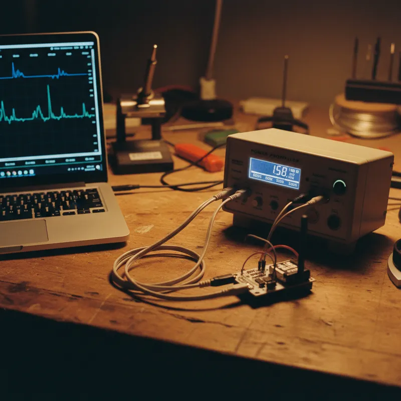
The Principle: Every Component Has a Signature
When an AC stimulus is applied across a component (or between any two nodes on a PCB), the resulting voltage-current relationship traces a characteristic curve on a V-I plot. This curve is the component’s electrical fingerprint, determined by its impedance characteristics at the test frequency.
Understanding these signatures is the foundation of effective VI curve analysis. Whether you are using a FADOS 9F1 or FADOS 7F1, the interpretation methodology is the same.
Passive Component Signatures
Resistors
A pure resistor produces a straight diagonal line on the VI plot. The slope of the line is determined by the resistance value:
- Low resistance (< 10 ohms): Nearly vertical line (high current at low voltage)
- Medium resistance (10 ohms – 10 kohms): Diagonal line at intermediate angles
- High resistance (> 10 kohms): Nearly horizontal line (low current even at higher voltage)
- Open circuit: Perfectly horizontal line (zero current at all voltages)
- Short circuit: Perfectly vertical line (zero voltage at all currents)
When probing across a resistor on a populated board, the signature may be modified by parallel components connected to the same nodes. This is expected, you are measuring the aggregate impedance of the node, not the isolated component.
Capacitors
A capacitor produces an elliptical (oval) signature on the VI plot. The width and orientation of the ellipse depend on:
- Capacitance value: Larger capacitance produces a wider ellipse (more current flows at the test frequency)
- ESR (Equivalent Series Resistance): Higher ESR tilts and distorts the ellipse toward a resistive (diagonal line) shape
- Leakage: A leaky capacitor shows an ellipse that is tilted, with asymmetric current flow
Key diagnostic patterns:
- Shorted capacitor: Ellipse collapses to a vertical line
- Open capacitor: Ellipse collapses to a horizontal line (or shows only the adjacent circuit’s signature)
- Degraded capacitor: Ellipse is narrower than the reference (reduced capacitance) or tilted (increased ESR)
Inductors
At the FADOS test frequencies, most inductors appear as near-short-circuits, their inductive reactance is low relative to their DC resistance. The VI signature of a standalone inductor is a steep diagonal line, almost vertical for low-DCR power inductors.
- Healthy inductor: Steep line reflecting the DC resistance
- Open inductor (cracked ferrite, broken wire): Horizontal line
- Shorted turns: The DC resistance decreases and the signature steepens slightly, this can be subtle and requires careful reference comparison
Semiconductor Signatures
Diodes
Diodes produce the most distinctive VI signatures, an asymmetric curve with:
- Forward bias region: Current increases sharply after the forward voltage threshold (approximately 0.6 V for silicon, 0.3 V for Schottky)
- Reverse bias region: Near-zero current (horizontal) until reverse breakdown
The resulting curve looks like a bent line or hockey stick shape, clearly different from any passive component.
Diagnostic patterns:
- Shorted diode: Symmetric vertical line (conducts equally in both directions)
- Open diode: Horizontal line in both directions
- Leaky diode: Increased current in the reverse region
Transistors (BJT, MOSFET)
Transistors show junction signatures that depend on which pins you are probing:
- Base-Emitter (BJT): Standard diode signature (forward junction)
- Base-Collector (BJT): Standard diode signature (forward junction)
- Collector-Emitter (BJT): Back-to-back diode characteristic, asymmetric but conducting in both directions
- Gate-Source (MOSFET): High-impedance capacitive signature (the gate oxide capacitance)
- Drain-Source (MOSFET): Body diode signature (forward in one direction, blocking in the other)
Integrated Circuits
IC pins show complex signatures because each pin connects to internal ESD protection diodes, input/output buffers, power rails, and functional circuitry. The key insight is that you do not need to understand the internal circuit to diagnose faults, you only need to compare the measured signature against a known-good reference.
Common IC fault patterns:
- Damaged ESD protection: Pin-to-GND signature loses its characteristic diode clamp shape
- Internal latch-up damage: Multiple pins show abnormally low impedance to power rails
- Bond wire failure: Pin shows open or intermittent signature (may change when board is flexed)
The Comparison Method
Individual signature interpretation is useful, but the most powerful diagnostic approach is comparative:
- Measure the suspect board at each test point
- Compare against a golden reference (stored from a known-good board)
- Identify deviations: the FADOS software overlays curves and highlights differences
- Interpret deviations using the signature patterns described above
This method works even for complex nodes where multiple components contribute to the aggregate signature. You do not need to decompose the signature into individual component contributions, you just need to identify that it differs from the expected pattern.
Building Diagnostic Skill
VI curve interpretation is a learnable skill that improves with practice. Start with simple boards, single-sided, through-hole components with clear access to individual parts. Graduate to dense SMT boards as your pattern recognition improves.
The FADOS software’s overlay display accelerates learning by making deviations visually obvious. After interpreting a few hundred faults, most technicians develop an intuitive ability to read signatures rapidly.
Why Buy FADOS from GSAS
GSAS Micro Systems is an authorized ProT Ar-Ge partner and ODM assembler. We provide operator training that covers the complete signature interpretation methodology described in this guide.
Training and support at our offices in Bengaluru, Hyderabad, Chennai, Pune, Mumbai, and Delhi NCR.
- INR invoicing with GST-compliant documentation
- Hands-on training with your specific board types
- Demo units available for evaluation
Also appears in:
Interested in ProT Ar-Ge tools?
Talk to our application engineers for personalized tool recommendations.
More from ProT Ar-Ge
View all →
FADOS Test Reports and GSAS Agent: Turning Board Test Results into an Auditable Record
4 Aug · 8 min

FADOS Circuit Board Tester: Complete Guide for Indian Repair Teams
16 Apr · 13 min

FADOS XI Frequency Scanning and VI Curve Tracing for PCB Diagnostics
16 Apr · 11 min
FADOS XI Non-Contact Short Circuit Detection: Find PCB Shorts in Seconds
16 Apr · 9 min

Emulating Processor Power for Thermal Testing: Why Constant Power
7 Oct · 7 min

CRPS and Rack Power Supply Testing: The Six Tests That Matter
7 Oct · 7 min


