
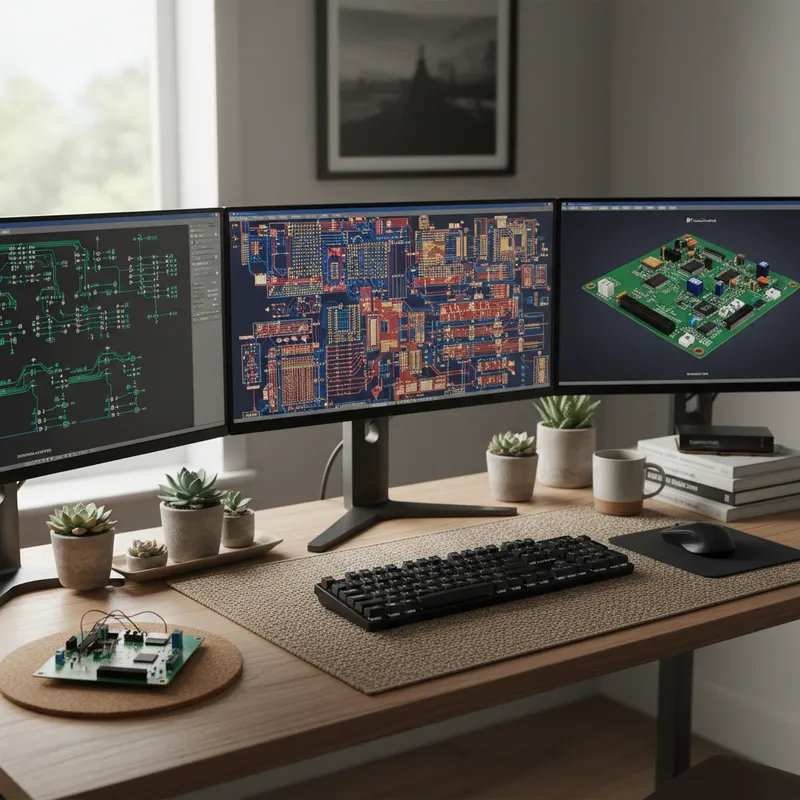
# From Schematic to Fabrication: The Complete Siemens EDA PCB Design Flow
The PCB design process involves a series of interdependent stages, each feeding data to the next. When these stages are handled by disconnected tools, the design flow becomes an exercise in data translation, exporting from one tool, importing into another, reconciling differences, and hoping nothing was lost in transit.
The Siemens EDA PCB design flow eliminates these translation gaps by providing an integrated path from schematic capture through manufacturing output. This article walks through each stage of the flow, from initial component selection to final fabrication handoff, showing how integration between stages reduces errors and accelerates time-to-board.
Stage 1: Component Selection with PartQuest
Every board design begins with component selection, and every experienced engineer knows that the wrong component choice at the start can invalidate weeks of downstream work. A part that goes end-of-life during your design cycle, a component with 52-week lead times, or a package with incorrect footprint data, any of these can force a late-stage redesign.
PartQuest is Siemens’ component intelligence platform, providing access to over 600 million parts with real-time parametric data. The key capabilities for Indian design teams:
Parametric Search: Filter components by electrical parameters, package type, operating temperature range, and availability. For Indian defence applications requiring extended temperature range (-40 to +85C or wider), this filtering eliminates unsuitable parts early. Supply Chain Awareness: PartQuest integrates Supplyframe supply chain data showing real-time availability, distributor stock levels, and lifecycle status. For Indian teams sourcing through both international and domestic channels, the supply chain visibility reduces procurement risk. Verified Models: Schematic symbols, PCB footprints, and 3D models sourced from manufacturer data. Using verified models eliminates the footprint errors that are among the most common causes of PCB re-spins.
Stage 2: Schematic Capture
With components selected, schematic capture translates the circuit design into a formal netlist. The Siemens schematic editor (in Xpedition) provides hierarchical schematic design, where complex systems are decomposed into functional blocks that can be designed, reviewed, and reused independently.
Hierarchical Design: A telecom base station board might have power management, digital processing, RF front-end, and interface blocks. Each block is a separate schematic sheet with automatically maintained connectivity between blocks. Cross-Probing: Select a component or net in the schematic, and the corresponding element highlights in the layout (and vice versa). Essential during debugging, trace a problem from the physical board back to the schematic intent instantly. Design Reuse: Proven circuit blocks can be saved as reusable blocks with associated constraints. Indian design teams working across product families benefit directly: a verified DDR interface can be instantiated on the next board with routing constraints intact.
Stage 3: Constraint Definition
Constraint-driven design is where the Siemens flow diverges fundamentally from a draw-then-check methodology. Before layout begins, the designer defines the electrical and physical rules that govern the design:
Impedance Targets: Specify target impedance for controlled-impedance nets (e.g., 50 ohms single-ended, 100 ohms differential for USB, 85 ohms differential for PCIe). The tool calculates required trace widths based on the stackup and enforces them during routing. Length Matching: Define maximum length mismatch within net groups (e.g., DDR data bus must be matched to within 5mm). The router will flag violations during routing, not after. Spacing Rules: Net-to-net spacing requirements based on voltage, frequency, or signal class. High-voltage nets get more clearance. Sensitive analogue signals get guard traces. Clock signals get isolation from noisy digital buses. Differential Pair Parameters: Pair spacing, impedance, length matching, and via transitions for differential pairs. Define once, enforce on every pair throughout the board. Class-Based Rules: Group nets by function (DDR, PCIe, power, analogue) and apply rules by class. When you add a new DDR net to the DDR class, it automatically inherits all DDR constraints.
The constraint manager is the single source of truth for design rules. Every downstream stage, placement, routing, verification, references these constraints. This eliminates the class of errors where a designer routes a trace correctly by the schematic intent but incorrectly by the electrical requirements, because the electrical requirements were not formally captured in the tool.
Stage 4: Component Placement
Placement determines the physical arrangement of components on the board. Good placement makes routing feasible; bad placement makes even the most capable autorouter produce suboptimal results.
Placement-Driven Analysis: HyperLynx DRC runs placement-level checks before routing: power plane coverage, decoupling capacitor proximity, and thermal hot spot flagging based on component power dissipation. 3D Clearance Checking: For designs with mechanical constraints, enclosures, connectors with specific mating heights, heat sinks, 3D checking ensures components physically fit. Critical for compact industrial and IoT enclosures common in Indian product designs. Placement Reuse: Proven placement patterns can be saved and reused, preserving validated configurations across product families.
Stage 5: Routing
Routing connects the placed components according to the netlist while respecting all defined constraints. The Siemens tools provide three routing approaches:
Interactive Routing: The designer manually guides each trace, with the tool providing real-time constraint checking, push-and-shove, and impedance display. This gives the designer full control over critical nets, clock distribution, high-speed serial links, sensitive analogue signals. Sketch Routing: The designer draws approximate paths for traces or buses, and the tool converts these sketches into DRC-clean routes that respect all constraints. Sketch routing is particularly efficient for memory buses and parallel interfaces where many traces follow similar paths. The designer provides the intent (this bus goes from here to there, through this corridor), and the tool handles the detail routing. Autorouting: For high pin-count devices and dense interconnect, the autorouter handles the connections automatically within the defined constraint framework. The autorouter respects impedance targets, spacing rules, length matching, and differential pair parameters. It is most effective when the constraints are well-defined and the placement is optimised, which is why the earlier stages matter so much.
Most real designs use a combination of all three. Critical nets are routed interactively, buses are sketch-routed, and the remaining connections are autorouted. The constraint system ensures consistency regardless of which routing method is used.
Stage 6: In-Design Verification
This is where the shift-left philosophy materialises in the Siemens flow. Verification is not a separate step after routing, it happens continuously during and after routing within the layout environment.
HyperLynx DRC: Over 100 automated electrical checks covering SI, PI, EMI, and high-speed rules. These run on the in-progress layout without export or translation. A designer can route a critical DDR interface, run SI checks on those specific nets, confirm compliance, and move on to the next section, all without leaving the layout environment. Signal Integrity Analysis: Pre-layout estimation and post-layout extraction for critical nets. Eye diagram analysis, timing margin calculation, and S-parameter extraction for high-speed interfaces. For Indian teams designing DDR5 or PCIe Gen5 interfaces, this analysis is essential for first-pass success. Power Integrity Analysis: PDN impedance analysis, decoupling optimisation, and voltage drop simulation. Ensures that the power delivery network meets the target impedance across the frequency range of interest, from DC resistance through the high-frequency regime where decoupling capacitors and plane resonances dominate. Thermal Analysis: Steady-state and transient thermal simulation to identify hot spots and verify that junction temperatures remain within component ratings. Critical for power electronics, motor drives, and enclosed industrial products common in Indian applications.
Stage 7: ECAD-MCAD Co-Design
PCB design does not exist in isolation. The board must fit within a mechanical enclosure, interface with connectors and cables, accommodate heat sinks and airflow paths, and avoid interference with other mechanical components.
The Siemens ECAD-MCAD co-design capability establishes a bidirectional link between the PCB layout environment and mechanical CAD tools. Changes in either domain propagate to the other:
- A mechanical engineer moves a connector to accommodate a cable routing change; the PCB designer sees the new connector position in the layout.
- A PCB designer adds a tall component that was not in the original mechanical model; the mechanical engineer sees the height conflict.
- Board outline changes, mounting hole relocations, and keep-out zone modifications are synchronised between domains.
This eliminates the sequential handoff where the mechanical design is “frozen” before PCB layout begins. For Indian teams building products with tight enclosures, industrial DIN-rail modules, handheld instruments, automotive ECUs, this co-design capability prevents the physical integration issues that traditionally surface during first prototype assembly.
Stage 8: Manufacturing Handoff
The final stage translates the verified design into manufacturing data. The Siemens flow supports multiple output formats:
ODB++: Siemens’ intelligent manufacturing data format carrying design intent, net connectivity, and component data, enabling the fabricator to perform DFM analysis using complete design context, not just bare geometry. IPC-2581: The industry-standard open format with rich data beyond Gerber-level geometry, including net information, component data, and stackup details. Gerber/NC Drill: Traditional outputs for fabricators that require them, generated from the same design data. Valor NPI DFM: Before generating outputs, Valor NPI checks the design against actual fabricator capabilities, minimum trace widths, via sizes, solder mask tolerances, annular ring requirements, all validated against the specific manufacturer’s process window.
The Integration Advantage
The thread running through every stage of this flow is integration. Each stage works from the same design database. Constraints defined in Stage 3 are enforced in Stages 5 and 6. Component data from Stage 1 carries through to manufacturing outputs in Stage 8. Mechanical constraints from Stage 7 are visible during placement in Stage 4.
This eliminates the export-import cycles that plague workflows built on disconnected tools. There is no Gerber export from the layout tool followed by Gerber import into the DFM tool. There is no manual netlist transfer from schematic to layout. There is no spreadsheet-based constraint communication between the SI engineer and the layout designer.
For Indian design teams, whether you are building a 4-layer IoT gateway in a startup or a 30-layer defence radar module in a large organisation, this integration translates directly into fewer errors, faster design cycles, and higher confidence at fabrication.
See the Flow in Action
GSAS Micro Systems provides demonstrations of the complete Siemens EDA design flow tailored to your design challenges, DDR5 routing, DFM validation, ECAD-MCAD integration, or the full end-to-end workflow.
Contact GSAS to schedule a design flow demonstration. Reach us through gsasindia.com or visit any of our offices in Bengaluru, Hyderabad, Chennai, Coimbatore, Pune, and Delhi NCR.
Also appears in:
Interested in Siemens EDA tools?
Talk to our application engineers for personalized tool recommendations.
More from Siemens EDA
View all →
India's EDA Moment: Why Design Tool Demand Is Growing, and the Engineering Careers It Creates
21 Sept · 9 min

AI and Complexity Are Redrawing EDA: Siemens on the Trillion-Transistor Era
13 Sept · 6 min

Calibre Vision AI: Bringing Order to DRC Debug at Advanced Nodes
24 Aug · 4 min

Siemens EDA EBS Expert Series: 6 Free PCB Design Webinars (Jul-Aug 2026)
20 Jul · 8 min

Emulating Processor Power for Thermal Testing: Why Constant Power
7 Oct · 7 min

CRPS and Rack Power Supply Testing: The Six Tests That Matter
7 Oct · 7 min


