Two Approaches to Production Programming
Indian electronics manufacturers face a fundamental choice in their production programming strategy: gang programming (offline, before assembly) or inline ISP programming (on-board, integrated into the SMT line). Each approach has distinct advantages and trade-offs that affect throughput, quality, cost, and flexibility.
Understanding these trade-offs is essential for making the right investment decision, a decision that affects production efficiency for years.
Gang Programming: Offline, Before Assembly
In gang programming, bare IC components are programmed before they are assembled onto PCBs. Multiple devices (4, 8, 16, or more) are placed in programming sockets simultaneously and programmed in parallel. After programming and verification, the devices are returned to tape or tray for pick-and-place feeding.
How It Works
- Devices arrive from the component supplier in tape-and-reel or tray packaging, unprogrammed
- Operator (or automated handler) transfers devices from tape/tray to programming sockets
- The gang programmer programs all devices in parallel
- Programmed devices are verified (read-back comparison)
- Devices are returned to tape/tray for SMT assembly
- Programmed devices are loaded into pick-and-place feeders
Advantages
- High parallelism: 8, 16, or more devices programmed simultaneously
- No PCB dependency: programming does not require board-specific fixtures; the same socket works for all boards using that device package
- No SMT line impact: programming happens separately from the assembly line; SMT cycle time is unaffected
- Simple setup: no custom fixtures per board design
Limitations
- Component handling: devices must be removed from packaging, programmed, and repackaged. Each handling step introduces ESD risk and mechanical stress
- No board-level verification: programming is verified in the socket, not in the final circuit. Solder defects that affect the programming interface are not detected until later testing
- Inventory complexity: programmed components must be tracked separately from unprogrammed stock. Firmware version management across multiple reels/trays adds logistics burden
- Device damage risk: socket insertion and extraction can damage fine-pitch leads (QFP, QFN packages)
Inline ISP Programming: On-Board, In the Line
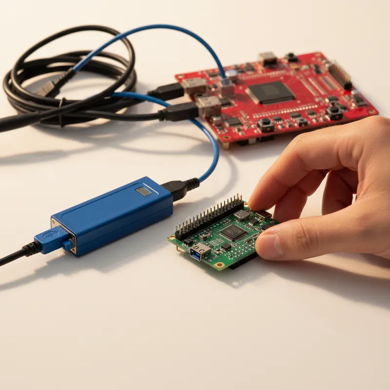
In-System Programming (ISP) programs devices after they are soldered to the PCB. A programming fixture with spring-loaded probes (pogo pins) contacts programming test points on the assembled board. The fixture connects to a programmer that loads firmware through the device’s ISP interface (JTAG, SWD, SPI, or similar).
How It Works
- PCBs arrive from SMT assembly with devices soldered but unprogrammed
- Boards enter the inline programmer via SMEMA conveyor
- Fixture probes contact the board’s programming test points
- Programmer loads firmware through the ISP interface
- Read-back verification confirms correct programming
- Boards continue downstream (pass to next station, fail to reject lane)
ProMik’s XTL-i (fully automated), XTL-s (compact inline), and XTL-m (manual) are ISP systems designed for this workflow.
Advantages
- Board-level verification: programming in the final circuit context confirms solder joint integrity and board-level connectivity
- No component handling: devices are never removed from their packaging until SMT placement; no additional handling after soldering
- Multi-device programming: all programmable devices on a single board can be programmed in one fixture engagement
- Firmware flexibility: firmware can be selected per board at production time (e.g., based on barcode scan), supporting late-stage variant configuration
- Direct MES integration: inline systems integrate with the production line’s MES for real-time traceability
Limitations
- Custom fixtures: each board design requires a dedicated programming fixture (additional cost and lead time per product)
- SMT line cycle time: programming adds to the total line cycle time; the programmer must keep up with upstream stations
- Board design dependency: PCB must include accessible programming test points in the layout
- Fixture wear: spring-loaded probes have finite life and require periodic replacement
Side-by-Side Comparison
| Factor | Gang Programming | Inline ISP |
|---|---|---|
| Programming point | Before assembly (bare IC) | After assembly (on PCB) |
| Parallelism | 8-64 devices simultaneously | 1-4 devices per board |
| Board-level verification | No | Yes |
| Component handling | Yes (ESD risk) | No |
| Custom fixture per board | No | Yes |
| SMT line impact | None | Adds cycle time |
| Multi-device per board | Separate operations | Single fixture engagement |
| Late-stage variant selection | Difficult | Easy (barcode-driven) |
| MES integration | Limited | Full (OPC-UA, REST API) |
| Traceability | Per-device | Per-board (full context) |
When to Choose Each Approach
Gang Programming Is Better When
- Production uses a single device type across many different board designs (the same socket serves all products)
- Production volumes are very high for a single device and the offline programming buffer does not constrain throughput
- The device package is robust enough for socket insertion/extraction (DIP, large QFP)
- Board-level programming test points cannot be added to the PCB layout
Inline ISP Is Better When
- Boards contain multiple programmable devices that benefit from single-fixture programming
- Automotive or safety-critical quality standards (IATF 16949) require board-level verification and full traceability
- Production requires late-stage firmware variant selection based on customer orders
- The board design includes accessible ISP test points
- MES integration and Industry 4.0 connectivity are production requirements
The Hybrid Approach
Many Indian manufacturers use both approaches in the same facility. Gang programmers handle high-volume commodity devices (SPI flash, simple MCUs) where the device type is shared across products. Inline ISP systems handle complex boards with multiple programmable devices, variant management requirements, and automotive traceability needs.
ProMik’s ecosystem supports this hybrid approach: the MSP2100Net lab programmer and XDM-USB handle development and small-batch programming at the bench, while the XTL-m, XTL-s, and XTL-i provide inline ISP at increasing automation levels. FlashTask Pro project files transfer across all systems.
Cost Considerations for Indian Manufacturers
For contract electronics manufacturers in Bengaluru, Chennai, Pune, and Noida handling multiple customers:
- Gang programmers offer lower per-product setup cost (no custom fixtures) but higher per-device handling cost
- Inline ISP systems have higher per-product setup cost (custom fixtures) but lower per-device cost (no handling, integrated verification)
- The crossover point depends on production volume, device complexity, and quality requirements
For automotive tier-1 suppliers where IATF 16949 traceability is mandatory, inline ISP with full MES integration is typically the only acceptable approach regardless of volume.
Why Buy from GSAS
GSAS Micro Systems is the authorised ProMik engineering partner in India, providing both bench-level and production programming systems with INR invoicing, fixture sourcing, and production workflow consultation. Engineering teams in Bengaluru, Hyderabad, Chennai, Pune, Mumbai, Delhi NCR, and Visakhapatnam help manufacturers evaluate programming approaches and implement the right solution for their production requirements.
Explore the ProMik product range or contact us for system evaluation and production planning consultation.
Also appears in:
Interested in ProMik tools?
Talk to our application engineers for personalized tool recommendations.
More from ProMik
View all →
Automotive ECU Programming and Traceability: Meeting IATF 16949 with ProMik
5 Apr · 7 min

Scaling Electronics Manufacturing in India: Programming Infrastructure for Growth
5 Apr · 7 min
FlashTask Pro: Production Programming Project Management with ProMik
5 Apr · 7 min

Production IC Programming: A Guide for Indian Electronics Manufacturers
5 Apr · 7 min

Emulating Processor Power for Thermal Testing: Why Constant Power
7 Oct · 7 min

CRPS and Rack Power Supply Testing: The Six Tests That Matter
7 Oct · 7 min