
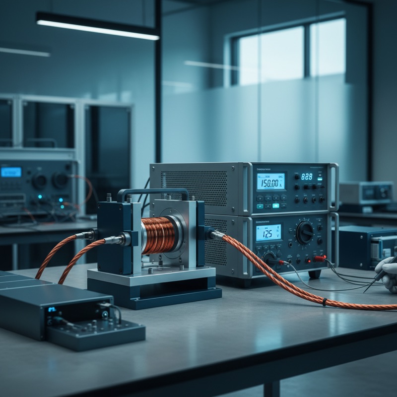
A single AI server rack can draw 40 kW or more. The power delivery network converting 48 V bus power down to the sub-1 V rails that feed GPU and accelerator dies relies on multiphase buck converters, each phase carrying tens of amps through its output inductor. The inductors in these converters are not passive bystanders, they are the energy storage elements that determine converter stability, transient response, and efficiency. And their performance changes dramatically under load.
An inductor rated at 470 nH at zero current may drop to 300 nH or less at its rated DC bias. That inductance drop is not a defect, it is the physics of magnetic saturation. But if the drop is steeper or earlier than specified, the converter’s control loop loses stability margin, output ripple increases, and thermal dissipation rises. In a server rack running 24/7, these effects compound into reliability problems that surface months after deployment.
This is why DC bias current testing matters. It is the only measurement that reveals how an inductor actually behaves at the currents it will carry in operation.
What DC Bias Testing Measures
A conventional LCR meter measures inductance at a small AC signal with no DC current flowing. This provides the nominal inductance value, useful for sorting and incoming inspection, but incomplete for power inductor characterization.
A DC bias test system superimposes a controlled DC current onto the AC measurement signal, measuring inductance as a function of DC bias. The result is a saturation curve: inductance plotted against DC current, showing exactly where the inductor begins to saturate and how quickly inductance falls off.
The Microtest DC Bias Current Source system delivers DC bias currents up to 640 A through the 6243H module, covering everything from small signal inductors to the high-current power inductors used in server power supplies and EV inverters.
Key Measurement Capabilities
Saturation current (Isat) scanning. The system sweeps DC current from zero to maximum, recording inductance at each step. The resulting curve reveals Isat, the current at which inductance drops by a specified percentage (typically 20-30%). This is the critical parameter for power inductor selection.
Temperature rise current (Irms) scanning. Using copper temperature coefficient measurements, the system evaluates the DC resistance change as the inductor heats under sustained DC current. Irms, the current at which the inductor reaches its rated temperature rise, determines the thermal limit distinct from the magnetic saturation limit.
DCR measurement. Built-in DC resistance measurement provides the resistive loss data needed for efficiency calculations. In multiphase converters where each milliohm of inductor DCR translates to watts of heat dissipation, accurate DCR data is essential.
Frequency response. The 6632+ system measures inductance under bias across 100 Hz to 10 MHz, while the 6350+ system covers 100 Hz to 500 kHz. The higher frequency range matters for characterizing inductors at their actual switching frequencies, 500 kHz to 2 MHz in modern server power stages.
Why This Matters for AI Server Supply Chains
The AI server market has created unprecedented demand for high-current, low-profile power inductors. Inductor manufacturers are scaling production rapidly, and component suppliers face pressure to verify incoming quality at volume. DC bias testing is the gatekeeper, the measurement that separates inductors that meet their saturation specifications from those that do not.
For power supply manufacturers in India supplying server OEMs, DC bias testing is becoming a procurement requirement rather than an optional characterization step. The test data, Isat curves, Irms ratings, DCR values, forms part of the component qualification report that server OEMs review during design-in and during ongoing quality audits.
Applications Beyond AI Servers
The same DC bias measurement capability applies across power electronics: PFC inductors in telecom rectifiers, filter inductors in variable frequency drives, common mode inductors in EMI filters, and power inductors in EV on-board chargers and DC-DC converters. In every case, the inductor operates under DC bias, and its actual performance under that bias determines system performance.
The Microtest DC Bias system supports testing of power inductors, common mode inductors, filter inductors, PFC inductors, and magnetic core materials, ferrite and alloy-based, with built-in permeability measurement.
Availability in India
GSAS is an authorized engineering partner in India, providing the complete DC Bias Current Test System portfolio with local support and INR invoicing. Our applications team supports inductor manufacturers, power supply designers, and incoming inspection operations across Bengaluru, Hyderabad, Chennai, Pune, Mumbai, Delhi NCR, and Visakhapatnam.
Also appears in:
Interested in Microtest tools?
Talk to our application engineers for personalized tool recommendations.
More from Microtest
View all →
Power Measurement for Server PSUs: Microtest 7140 Power Analyzer
7 Apr · 5 min
Wireless Charger QC Testing with the Microtest 9901
7 Apr · 5 min

Motor Stator Testing in EV Manufacturing: Microtest MT-6910 Series
7 Apr · 5 min
PCB Incoming Inspection with Multichannel LCR Testing
6 Apr · 5 min

Emulating Processor Power for Thermal Testing: Why Constant Power
7 Oct · 7 min

CRPS and Rack Power Supply Testing: The Six Tests That Matter
7 Oct · 7 min


