
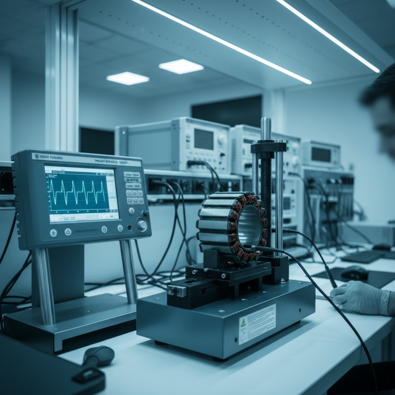
A motor or transformer with a shorted turn will pass a hipot test. The insulation between the shorted turn and adjacent windings, between windings and core, between windings and frame, all of that insulation remains intact. The hipot tester sees adequate insulation resistance and no breakdown. The product passes.
But the shorted turn creates a local heating zone. Current circulates in the shorted loop, dissipating power as heat. Over hours, days, or weeks of operation, the localised heating degrades the insulation further, eventually causing a cascade failure. The motor burns out. The transformer overheats. The field failure report arrives.
Impulse winding testing detects shorted turns before the product ships.
How Impulse Testing Works
The principle is straightforward. A fast-rise, high-voltage impulse is applied to the winding. The impulse excites the winding’s distributed inductance and capacitance, producing a damped oscillation, a ringing waveform whose shape is determined by the winding’s electrical characteristics. A good winding produces a characteristic waveform. A winding with a shorted turn, a layer short, or a misconnection produces a different waveform.
The tester captures the DUT waveform and compares it against a stored reference from a known-good sample. Deviations beyond programmed tolerance indicate a defect.
The Microtest 7750 Series
The Microtest 7750 Series Impulse Winding Tester implements this test with the resolution and speed needed for production environments.
200 MHz sampling rate at 9-bit resolution. The high sampling rate captures the fast initial transient and the subsequent ringing with sufficient time-domain resolution to detect subtle waveform differences. The 9-bit vertical resolution provides the amplitude discrimination needed to separate marginal defects from normal unit-to-unit variation.
Output voltage: 1200 V, 5200 V, or 10000 V depending on model. The voltage must be high enough to stress the turn-to-turn insulation and excite the winding’s resonant modes, but not so high as to damage good units. Different DUT types, small signal transformers, power transformers, motor stators, require different voltage ranges.
Lowest inductance: 0.1 uH. The system can test very low-inductance windings, just a few turns, where the impulse response is extremely fast and the waveform differences are subtle. This extends the test to coils, solenoids, and relay windings that many impulse testers cannot handle.
10 tests per second. Production throughput requires fast testing. At 10 tests per second, the 7750 keeps pace with automated winding machines and assembly lines.
Six Comparison Modes
The 7750 provides six algorithms for waveform comparison, each sensitive to different defect types:
| Mode | Detection Strength |
|---|---|
| AREA | Overall waveform energy difference, catches gross defects |
| DIFF | Point-by-point amplitude difference, sensitive to winding parameter changes |
| CORONA | High-frequency oscillation detection, identifies partial discharge in insulation |
| FLUTTER | Envelope variation detection, catches intermittent contacts and loose connections |
| LAPLACIAN | Second-derivative analysis, highlights inflection point shifts from impedance changes |
| WAVEFORM | Full waveform overlay, visual comparison for engineering diagnosis |
Using multiple comparison modes simultaneously increases defect coverage. A shorted turn that barely shifts the AREA metric may produce a clear signal in the DIFF or LAPLACIAN analysis.
Multi-Channel Testing: 7759
The Microtest 7759 extends the platform to multi-channel operation with 8+1 channels, eight DUT channels plus one reference channel. This enables simultaneous or sequential testing of multiple windings in a transformer, multiple phases in a motor stator, or multiple coils in a multi-element assembly, within a single test fixture and test cycle.
Applications
Motors. Stator windings in BLDC, induction, and universal motors. Turn-to-turn shorts in motor windings are the leading cause of premature motor failure.
Transformers. Power transformers, signal transformers, current transformers, pulse transformers. Interlayer insulation faults and shorted turns degrade transformer performance and create safety risks.
Generators. Field windings and armature windings in generators and alternators.
Ignition coils. Automotive ignition coils operate at high voltage and high temperature, making winding integrity testing essential for reliability.
Relays and electromagnets. Coil integrity verification before assembly into relay or solenoid housings.
Filters. EMI filter inductors and common mode chokes where winding faults degrade filtering performance.
Complementing Hipot Testing
Impulse winding testing does not replace hipot testing, it complements it. Hipot verifies insulation between isolated circuits (primary to secondary, winding to core). Impulse testing verifies insulation within a single winding (turn to turn, layer to layer). A complete quality test protocol for motors and transformers includes both.
The Microtest product line includes both hipot testers and impulse winding testers, and the motor stator test systems integrate both test types into a single automated platform.
Availability in India
GSAS is an authorized engineering partner in India, providing the 7750 Series and 7759 multi-channel impulse winding testers with local installation, fixture design support, and calibration. Our team supports motor, transformer, and coil manufacturers across Bengaluru, Hyderabad, Chennai, Pune, Mumbai, Delhi NCR, and Visakhapatnam.
Explore Microtest Impulse Winding Testers → | Request a Quote →
Also appears in:
Interested in Microtest tools?
Talk to our application engineers for personalized tool recommendations.
More from Microtest
View all →
Power Measurement for Server PSUs: Microtest 7140 Power Analyzer
7 Apr · 5 min

Wireless Charger QC Testing with the Microtest 9901
7 Apr · 5 min

Motor Stator Testing in EV Manufacturing: Microtest MT-6910 Series
7 Apr · 5 min
PCB Incoming Inspection with Multichannel LCR Testing
6 Apr · 5 min

Emulating Processor Power for Thermal Testing: Why Constant Power
7 Oct · 7 min

CRPS and Rack Power Supply Testing: The Six Tests That Matter
7 Oct · 7 min


