
In short
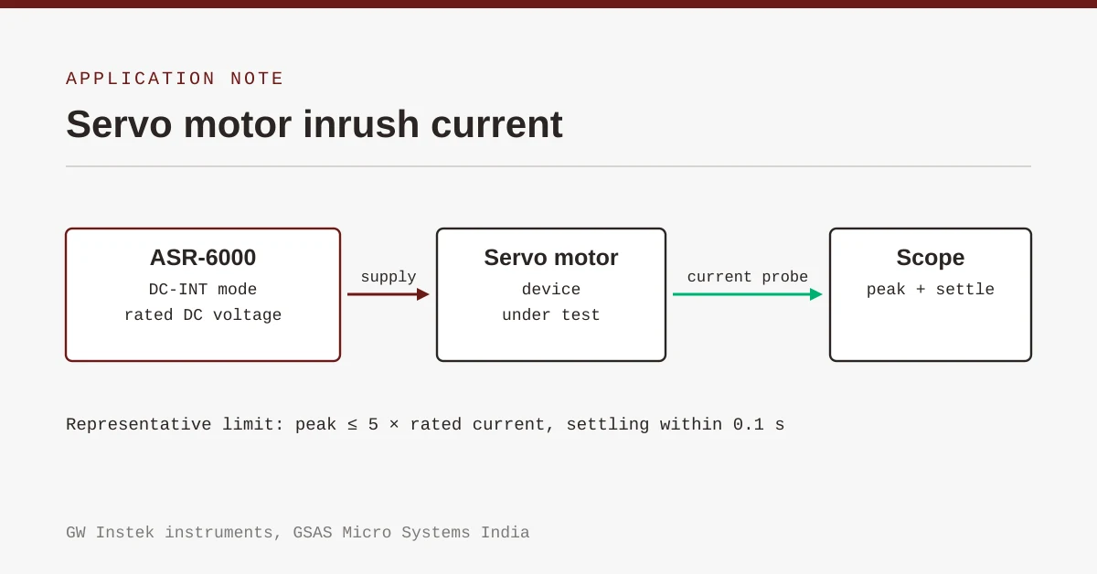
Servo motor inrush current is measured by powering the motor from a programmable DC source at its rated voltage and capturing the power-on current waveform with a current probe and oscilloscope. A representative acceptance limit is a peak below five times the motor's rated current, with the current settling back to the rated value within 0.1 seconds.
Power on a servo motor and the current it draws in the first few tens of milliseconds has very little to do with the current it draws while it is running. The drive’s bulk capacitance is empty, the motor is stationary, and the supply sees something close to a short circuit until the capacitors charge. The spike that follows is inrush current, and it is the number that decides the rating of every protective device upstream of the motor: the fuse, the contactor, the breaker, and the supply itself.
Getting that number wrong is expensive in both directions. Specify too low and the system nuisance-trips on every start. Specify too high and the protection no longer protects anything.
This note describes the test method as GW Instek’s application material sets it out, and is explicit about the parts of the measurement that decide whether the number you record is real.
The acceptance criterion comes from the specification, not the instrument
A representative servo inrush requirement, and the one used in GW Instek’s application material, is a peak inrush current no greater than five times the motor’s rated current, with the current returning to the rated value within 0.1 seconds.
Treat that as an example of the shape a requirement takes, not as a limit to test against. The limit is a system decision: it comes from the protective device you intend to use, the supply you intend to ship with, and your customer’s specification. Two motors with identical nameplate ratings can carry different inrush limits because the systems around them differ.
What the shape tells you is that an inrush specification always has two halves, and a test that reports only one of them is incomplete:
- An amplitude limit. How high the peak is allowed to go, usually expressed as a multiple of rated current.
- A time limit. How quickly the current must settle back to the rated value.
A motor that passes the amplitude limit but takes half a second to settle has not passed. Neither has one that settles in 20 ms with a peak at eight times rated.
The source has to supply the inrush, not limit it
The most common way to get a wrong answer is to use a supply that current-limits during the event. If the source folds back, what you have measured is the source’s protection threshold, not the motor’s inrush.
GW Instek’s application material runs this test with the ASR-6000 Series programmable AC/DC source configured in DC-INT mode, which is its internally generated DC output, programmed to the motor’s rated DC voltage. In the documented example that voltage is 28 VDC.
Two properties of the source matter here:
- Peak current headroom. The ASR-6000 supplies a maximum peak current of up to four times its rated RMS value, which is what lets it pass a capacitive inrush rather than clamp it.
- A programmable, repeatable output. Power-on has to happen the same way every run. A bench supply switched on by hand introduces a different rise time on every attempt, and the inrush follows the rise time.
The measurement chain decides the number
GW Instek’s application material is candid that it does not specify the measurement instrument, and leaves the oscilloscope and current probe to be chosen for the motor current and the bandwidth required. That is the right call, and it is also where most of the error lives. Four things to settle before you trust a reading:
Probe type and range. A clamp-on AC current probe will not see the DC component of the inrush. Use a probe with DC response, typically a Hall-effect or current-transformer-plus-Hall hybrid, rated well above the peak you expect. A probe operating near the top of its range saturates, and saturation reads as a flat top that looks like a well-behaved limit.
Bandwidth. The leading edge of a capacitive inrush is fast. If the probe and channel roll off below the edge rate, the recorded peak is lower than the real one, and the error is always in the unsafe direction.
Trigger and capture window. Trigger on the current rise, not on the supply command, and set the record length to cover the full settling period with margin. A 0.1 s settling requirement needs a capture window several times that to show the current actually staying down.
Dwell between runs. The drive’s bulk capacitors must be fully discharged before the next run or the measured inrush falls with every repeat. Fix a dwell time, write it in the procedure, and apply it.
What the waveform tells you beyond pass or fail
A pass or fail against the limit is the deliverable, but the shape of the current waveform is the engineering value:
- A peak that rises with supply voltage faster than proportionally points at the capacitor bank rather than the motor.
- A slow, drifting settle rather than a clean decay usually means the drive is still regulating, not that the inrush is still flowing.
- A second, smaller peak some milliseconds after the first is often the controller enabling the power stage, and it belongs in the report because the protective device sees both.
Record the supply voltage, the source mode, the probe and its range, and the dwell time alongside the waveform. An inrush figure without that context cannot be reproduced, and an inrush figure that cannot be reproduced will be argued about the first time a protective device trips in the field.
Where this sits in an Indian test plan
Inrush verification shows up on servo and motor-drive programmes across factory automation, packaging and machine tools, and on the 28 VDC equipment common in aerospace and defence-adjacent industrial work. It is normally a design-verification test that then becomes a sampled production test, which makes repeatability worth more than absolute precision: the same bench, the same probe, the same dwell, run the same way each time.
The same ASR-6000 bench covers the neighbouring tests, because the source is an AC/DC platform rather than a DC supply. Mains-side behaviour, voltage dips, phase loss and harmonic draw on the drive’s input side run on the same instrument in its AC modes, which is usually what makes the purchase worth it rather than the inrush test alone.
Instruments and support from GSAS
GSAS Micro Systems is an authorized GW Instek engineering partner for Karnataka, Andhra Pradesh and Telangana, supporting customers across India. We supply the ASR-6000 Series with application engineering on test-bench architecture, probe and measurement-chain selection, and calibration support, from Bengaluru, Chennai, Pune, Hyderabad, Mumbai and Delhi NCR.
If you want an inrush bench scoped against your own motor and protective-device specification, talk to us.
Source: GW Instek application material for the ASR-6000 Series. The acceptance limit quoted is the one in that material; your own limit comes from the applicable product specification.
Also appears in:
Interested in GW Instek tools?
Talk to our application engineers for personalized tool recommendations.
More from GW Instek
View all →
Emulating Processor Power for Thermal Testing: Why Constant Power
7 Oct · 7 min

CRPS and Rack Power Supply Testing: The Six Tests That Matter
7 Oct · 7 min

GPU Power Board Testing: DC Input Verification Before Integration
7 Oct · 6 min
Battery Simulator vs Battery Emulator: Hardware for BMS and Pack Testing
1 Sept · 7 min

SuperTest Van Gogh 6.0: C23, C++23 and the C++20 Modules Gap
6 Oct · 7 min

AI Inside the Engineering Process: What Is Worth Automating, and What Still Needs an Engineer
21 Sept · 11 min