
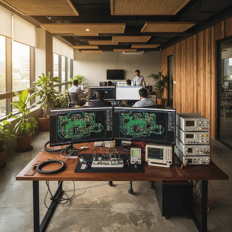
India is in the midst of a power electronics revolution. EV motor controllers, onboard chargers, solar string inverters, battery management systems, and industrial variable frequency drives all share a common requirement: they must switch high voltages and currents at high frequencies while maintaining thermal stability, electromagnetic compatibility, and long-term reliability.
Indian companies are designing these systems today. Major Indian auto OEMs are developing next-generation EV platforms. Indian engineering conglomerates and Siemens India are deploying industrial drives and energy infrastructure.
Dozens of startups are building solar inverters and EV charging equipment. All face the same challenge: power electronics PCB design is significantly more demanding than conventional digital board design, and tools that work for an evaluation board are inadequate for a 10 kW solar inverter or a 50 kW motor controller.
HyperLynx, Siemens EDA’s signal integrity and power integrity analysis platform, combined with Xpedition’s high-current layout capabilities, addresses the electrical side of power electronics design, and pairs with CFD thermal simulation for the thermal side.
The Power Electronics Design Challenge
Power electronics PCBs differ from conventional digital boards in several fundamental ways:
High Currents. A solar inverter’s DC bus may carry 20-50 amperes. An EV motor controller’s phase outputs may handle 100 amperes or more. These currents flow through PCB copper that must be dimensioned not just for DC resistance but for thermal rise. A trace that is electrically adequate may still fail thermally if the copper cross-section is insufficient to dissipate the resistive heating. High Voltages. EV battery packs operate at 400V or 800V. Solar inverter DC buses may reach 1000V. These voltages require creepage and clearance distances that dominate the board layout, consuming board area and constraining component placement in ways that digital designers rarely encounter. Fast Switching. Modern power semiconductors, particularly wide-bandgap devices based on silicon carbide (SiC) and gallium nitride (GaN), switch at speeds that create signal integrity and electromagnetic compatibility challenges rivalling those of high-speed digital design. A SiC MOSFET switching at 100 kHz with a 50 ns rise time has a knee frequency around 7 MHz, and the ringing that rides on those edges pushes usable spectral content well above it. The PCB layout must manage this frequency content or face conducted and radiated emissions that fail EMC testing. Thermal Management. Power dissipation in a motor controller or inverter can reach hundreds of watts. The PCB is not merely a signal carrier, it is a thermal management structure. Copper planes conduct heat from power devices to heat sinks. Thermal vias transfer heat between layers. The PCB material itself must withstand sustained elevated temperatures without degradation.
Power Delivery Network Analysis with HyperLynx PI
HyperLynx PI (Power Integrity) provides the analysis capabilities that power electronics designers need to validate their PCB’s power distribution before fabrication.
DC Drop Analysis
DC drop analysis calculates the voltage drop across copper planes and traces under DC current loading. For a power electronics PCB, this analysis answers critical questions:
- What is the voltage drop from the DC bus capacitors to the gate driver power pins?
- Is the sense trace to the current sensor maintaining adequate voltage accuracy?
- Are the copper planes dimensioned to carry the required current without excessive temperature rise?
In a solar inverter, a 50-ampere DC bus current flowing through an undersized copper plane creates voltage drops that reduce conversion efficiency and generate localised heating. HyperLynx PI maps voltage drop across the entire PCB, identifying bottlenecks before fabrication. For Indian teams targeting BIS efficiency requirements, DC drop analysis is the difference between meeting and missing targets.
AC Impedance Analysis
AC impedance analysis evaluates the power distribution network’s impedance as a function of frequency. For wide-bandgap devices switching at 100 kHz with 20-50 ns rise times, the range that matters runs from the switching frequency up past the edge-rate knee, roughly 7 to 18 MHz for those rise times, and higher again where layout parasitics ring. HyperLynx PI calculates the impedance profile, identifying resonances and high-impedance points that could amplify switching noise.
Decoupling Optimisation
Decoupling capacitors control power distribution network impedance, but placing them without analysis is guesswork. HyperLynx PI evaluates each capacitor, considering its value, ESR, ESL, placement, and connection inductance, and recommends an optimised strategy. A 100 nF capacitor placed 10 mm from a GaN half-bridge is functionally useless at 200 MHz due to connection inductance. HyperLynx PI quantifies this effect and guides the designer to effective solutions.
Wide-Bandgap Devices: New SI/PI Challenges
SiC and GaN power devices switch faster, operate at higher temperatures, and achieve higher efficiencies than conventional silicon IGBTs. Indian EV and solar inverter designs are increasingly adopting them, but faster switching creates new SI/PI challenges:
Gate Drive Loop Inductance. A SiC MOSFET’s gate driver must deliver high peak currents through a low-inductance loop. Parasitic inductance in the gate drive loop causes voltage ringing that can exceed the device’s maximum gate voltage rating, leading to device degradation or failure. HyperLynx can model the gate drive loop inductance and identify layout modifications that reduce it. Power Loop Inductance. The commutation loop, from the DC bus capacitors through the switching devices and back, must have the lowest possible inductance. Parasitic inductance in this loop causes voltage overshoot during switching that stresses the devices and increases switching losses. PCB layout is the primary tool for minimising power loop inductance, and HyperLynx PI provides the analysis to quantify the loop inductance of a specific layout. Common-Mode Noise. Fast switching transitions create common-mode currents that flow through parasitic capacitances, between the switching node and the heat sink, between the heat sink and the chassis, between the chassis and earth ground. These common-mode currents are a primary source of conducted EMI. Understanding and managing the parasitic capacitances that enable them requires 3D field analysis of the PCB and power module assembly.
The Thermal-Electrical Handoff
Power electronics design cannot separate electrical and thermal analysis. Temperatures affect copper resistance, semiconductor losses, and component reliability. The electrical side tells you where the power is dissipated, from the IR-drop and current-density results HyperLynx PI does produce; a CFD thermal solver tells you what that dissipation does to temperature once heat sinks, enclosures, and airflow are accounted for. In practice the two are separate tools with a manual handoff, not a coupled simulation: the per-device dissipation figures from the electrical side become boundary conditions you set up in the thermal model. GSAS supports Cradle CFD for the thermal half.
Doing both halves matters for Indian designs, where ambient temperatures in vehicle engine compartments and rooftop solar installations can reach 50 degrees Celsius. A design that works at 25 degrees on the bench may fail in a Rajasthan solar farm or a Chennai engine bay.
EMI/EMC Pre-Compliance
Power electronics are notorious EMI generators. Emissions must comply with CISPR 11 (industrial), CISPR 25 (automotive), and MIL-STD (defence). HyperLynx DRC catches common EMC problems during design:
- Switching noise coupling: Rules that verify adequate separation between noisy switching circuits and sensitive analogue or control circuits
- Conducted emissions paths: Analysis of the current return paths to identify loops that act as unintentional antennas
- Ground plane integrity: Verification that ground planes are continuous under sensitive circuits and that slots or splits do not force return currents through long detour paths
- Filter placement: Validation that EMI filter components are placed and routed to be effective, a common-mode choke with its input and output traces running in parallel on the same layer provides virtually no filtering
Catching EMC problems before the first prototype saves Indian teams months of debug time and re-spin costs.
Xpedition Layout for Power Electronics
Power electronics PCB layout differs significantly from digital board layout:
Thick Copper. Power boards commonly use 2-4 oz copper, which changes etching characteristics, minimum trace widths, and achievable clearances. High-Current Traces. Traces carrying 10-50 amperes must be dimensioned for DC resistance and thermal rise. Conductor sizing has to account for copper thickness, trace width and permitted temperature rise together, which is why IPC-2152 style derating belongs in the constraint set rather than in a designer’s head. Thermal Relief. Thermal vias under power device pads conduct heat to internal planes and heat sinks. Via count, diameter and pitch under those pads are constraint decisions worth fixing in the stackup rules rather than leaving to per-footprint judgement. Creepage and Clearance. Safety standards such as IEC 62368 and IEC 61800 set creepage and clearance distances that scale with working voltage, pollution degree and material group, so a 400 V or 800 V bus drives materially wider separations than logic-level design ever needs. The exact distances come from the standard’s own tables for your construction. Xpedition’s DRC enforces voltage-dependent clearance rules throughout layout.
Indian Applications
The breadth of power electronics applications in India is remarkable:
EV Motor Controllers. Major Indian auto OEMs and their Tier-1 suppliers are developing motor controllers for two-wheelers, three-wheelers, passenger cars, and commercial vehicles. These controllers manage 400V or 800V battery voltages, switching at 10-20 kHz, with SiC or GaN devices for maximum efficiency. Onboard Chargers. Every EV needs an onboard charger that converts AC mains power to DC battery voltage. Indian onboard charger designs must handle the country’s 230V/50Hz mains supply with its associated voltage variations and power quality issues. HyperLynx analysis ensures that the charger’s power stage and control circuits perform reliably across the full range of Indian mains conditions. Solar String Inverters. India’s solar build-out, part of a national target of 500 GW of non-fossil generating capacity by 2030, drives enormous demand for string inverters. These inverters convert the variable DC output of solar panel strings to grid-frequency AC, operating at switching frequencies of 20-100 kHz with DC bus voltages up to 1000V. Battery Management Systems. Every EV and grid-scale energy storage system requires a battery management system that monitors cell voltages, temperatures, and currents. The BMS PCB combines high-voltage isolation barriers with precision analogue measurement, a challenging combination that requires careful layout and thorough signal integrity analysis. Industrial Variable Frequency Drives. Indian engineering conglomerates, Siemens India, and other industrial automation suppliers manufacture variable frequency drives for motors ranging from fractional horsepower to hundreds of kilowatts. These drives use IGBT or SiC modules switching at 2-20 kHz, with PCBs that must handle high currents, high voltages, and aggressive EMC requirements simultaneously.
Getting Started with GSAS
GSAS Micro Systems provides specialised support for Indian power electronics teams adopting Siemens EDA tools, with guidance tailored to thick copper layout, high-voltage clearances, thermal management, and EMC compliance.
Contact GSAS Micro Systems today for a power electronics design review. Whether you are developing an EV motor controller, a solar inverter, a BMS, or an industrial drive, GSAS can evaluate your methodology and recommend tools that improve design quality and reduce your development cycle. Reach us through gsasindia.com or visit our offices in Bengaluru, Hyderabad, Chennai, Pune, Mumbai, and Delhi NCR.
Also appears in:
Interested in Siemens EDA tools?
Talk to our application engineers for personalized tool recommendations.
More from Siemens EDA
View all →
India's EDA Moment: Why Design Tool Demand Is Growing, and the Engineering Careers It Creates
21 Sept · 9 min

AI and Complexity Are Redrawing EDA: Siemens on the Trillion-Transistor Era
13 Sept · 6 min

Calibre Vision AI: Bringing Order to DRC Debug at Advanced Nodes
24 Aug · 4 min

Siemens EDA EBS Expert Series: 6 Free PCB Design Webinars (Jul-Aug 2026)
20 Jul · 8 min

Emulating Processor Power for Thermal Testing: Why Constant Power
7 Oct · 7 min

CRPS and Rack Power Supply Testing: The Six Tests That Matter
7 Oct · 7 min

