
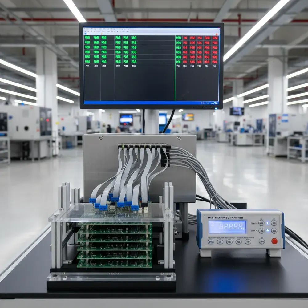
Manual VI curve tracing is a powerful diagnostic technique, but it has an inherent limitation: speed. A skilled technician probing a moderately complex board, say, 200 test points, needs 30 to 45 minutes per board. In a production environment processing dozens of boards daily, that arithmetic does not work. FADOS MUX scanning eliminates this bottleneck by automating the entire probe-compare-report cycle across up to 100 channels simultaneously.
The Problem with Manual Probing
Consider a typical scenario at an Indian EMS facility performing board-level repair for automotive ECUs. Each ECU has approximately 300 components. A technician must physically position probes on each component, wait for the signature to stabilize, visually compare it against a reference, note any deviation, and move to the next point, roughly 30 seconds per point.
At 300 points, a single board consumes 2.5 hours. If the facility handles 20 boards per shift, you need over 50 technician-hours. The math forces a compromise: test fewer points (and miss faults) or hire more technicians (and increase costs).
Beyond speed, manual probing introduces variability. Probe contact pressure affects readings. Fatigue leads to skipped points. Two technicians testing the same board may reach different conclusions. Automation solves all of these problems simultaneously.
FADOS MUX Architecture
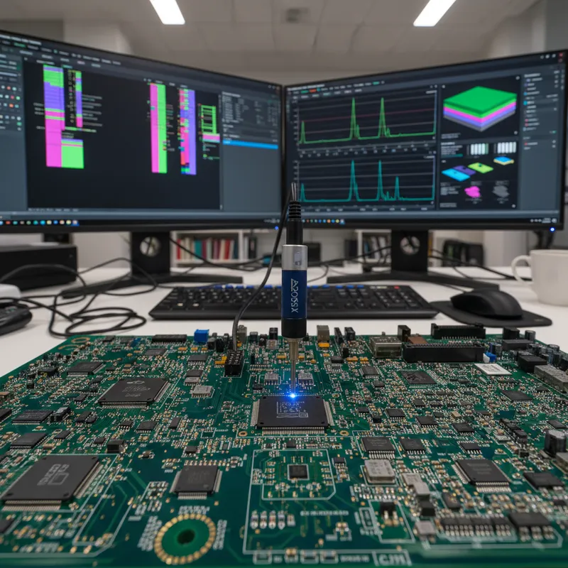
The FADOS MUX system extends any FADOS analyzer (9F1 or 7F1) with external multiplexer units. Each unit provides 96 switching channels. Multiple units can be daisy-chained for boards requiring more test points. The architecture has three layers.
Hardware Layer. The MUX unit connects each of its 100 channels to the FADOS measurement inputs through high-quality reed relays selected for low contact resistance and high switching life. A custom test fixture, bed-of-nails or pogo-pin jig, interfaces between the MUX channels and the board under test. Control Layer. The FADOS software orchestrates the scanning sequence: connect channel 1, trigger measurement, store result, disconnect, connect channel 2, repeat. The entire 100-Channel sweep completes in under two minutes, compared to 48 minutes for manual probing. Analysis Layer. Each measured signature is compared against a stored golden reference. The software computes deviation metrics and flags channels exceeding configurable thresholds. The result is a colour-coded pass/fail map of the entire board, generated automatically.
Golden Board Learning
The foundation of MUX scanning is the golden board reference library.
Select reference boards. Choose three to five known-good boards from the same production batch. Using multiple references accounts for normal manufacturing variation, component tolerances, solder joint differences, PCB trace impedance spread. Capture signatures. Mount each reference board on the test fixture and run the full 100-Channel scan. The software stores each channel’s VI signature with metadata, test frequency, signal amplitude, channel number, timestamp. Compute tolerance envelopes. The software analyses all reference signatures for each channel and computes acceptance bands. Channel 14, for instance, might show resistance ranging from 985 to 1,015 ohms across five boards. The software sets the window accordingly with configurable margin, eliminating false failures from normal component spread. Build multi-frequency profiles. Capture references at multiple frequencies, typically 100 Hz, 10 kHz, and 500 kHz. Each frequency excites different failure modes, and the combined profile catches faults any single frequency would miss.
Automatic Comparison and Reporting
Production scanning is straightforward once the reference library exists.
Load the board. Place the board under test on the fixture. Pneumatic or vacuum holddowns ensure consistent pogo pin contact pressure. Start the scan. A single button press, or a trigger from the production line’s MES, initiates the automated sweep. Review results. Within two minutes, the software presents a visual board map. Green channels passed. Red channels failed. Yellow channels are marginal. Drill down. Click any failed channel to see the measured signature overlaid on the golden reference. A collapsed curve indicates a short; a flattened curve indicates an open; a shifted knee indicates a degraded semiconductor. Generate reports. PDF or CSV output documents every channel’s result for quality records, customer deliverables, or regulatory compliance. Serial number tracking links each report to a specific board.
Fixture Design Considerations
The test fixture is the critical interface between MUX and board. Good design determines reliable results versus false failures.
Test point selection. Not every component needs a channel. Prioritize high-value and high-failure-rate components: power semiconductors, electrolytic capacitors, voltage regulators, connectors. A well-chosen 60 to 80 test points typically covers 90 percent of common failure modes. Pogo pin selection. Rate pins for expected cycle count, a production fixture seeing 100 cycles daily for five years needs pins rated for 125,000+ cycles. Spring force must balance reliable contact against avoiding board damage. Ground reference. The fixture must provide solid, low-impedance ground connections to the board’s ground plane. Multiple distributed ground pins prevent ground bounce from corrupting measurements at higher frequencies.
Production Line Integration
MUX scanning fits into production workflows at several points.
Incoming inspection. Screen assemblies from contract manufacturers before they enter your line, catching soldering defects, wrong-value components, and missing parts early. Post-reflow verification. Verify that thermal processing has not damaged components, particularly moisture-sensitive devices and large BGAs. Final test augmentation. Functional test catches boards that do not work. MUX scanning catches boards with marginal components that will fail in the field. Combining both dramatically reduces warranty returns. Repair verification. After board-level repair, scan to confirm the original fault is resolved and that the repair process has not introduced secondary damage.
ROI for Indian EMS Facilities
The business case is straightforward. A facility processing 50 boards per day: manual approach consumes 37.5 technician-hours daily (50 boards at 45 minutes each). MUX approach consumes 2.5 hours (50 boards at 3 minutes each). The labour savings, approximately 35 technician-hours per day, typically recover the system investment within six to nine months. Quality improvements accelerate payback further.
Setting Up MUX Scanning with GSAS
GSAS Micro Systems provides the complete FADOS MUX scanning solution in India, including the analyzer, MUX expansion units, fixture design consultation, and operator training. We support every phase, from test point selection through golden board library creation and production integration.
Contact GSAS at gsasindia.com to schedule a demonstration with your own boards and discuss a deployment plan tailored to your production volume.
Also appears in:
Interested in ProT Ar-Ge tools?
Talk to our application engineers for personalized tool recommendations.
More from ProT Ar-Ge
View all →
FADOS Test Reports and GSAS Agent: Turning Board Test Results into an Auditable Record
4 Aug · 8 min
FADOS Circuit Board Tester: Complete Guide for Indian Repair Teams
16 Apr · 13 min
FADOS XI Frequency Scanning and VI Curve Tracing for PCB Diagnostics
16 Apr · 11 min
FADOS XI Non-Contact Short Circuit Detection: Find PCB Shorts in Seconds
16 Apr · 9 min

Emulating Processor Power for Thermal Testing: Why Constant Power
7 Oct · 7 min

CRPS and Rack Power Supply Testing: The Six Tests That Matter
7 Oct · 7 min


