
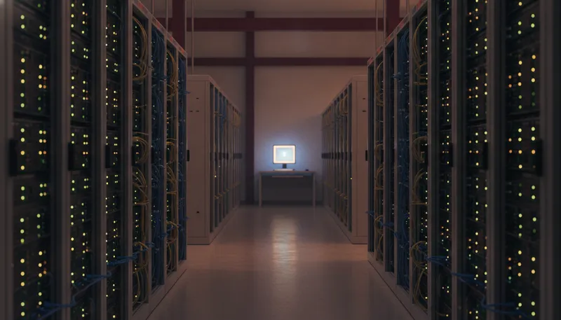
A debug probe used to be a personal tool: one engineer, one USB cable, one target. That model breaks the day your team shares expensive target hardware, or your firmware needs to be tested on a rack of real boards on every merge. SEGGER’s answer has two layers: J-Link Remote Server, a free utility that puts any USB J-Link on the network, and the J-Link PRO family, probes with Ethernet built in.
This guide covers both, with the setup commands, and how Indian firmware teams wire them into hardware-in-the-loop CI/CD.
Layer 1: J-Link Remote Server, any J-Link on the network
J-Link Remote Server ships free in the J-Link Software and Documentation Package (Windows, macOS, Linux, including Linux Arm). SEGGER’s knowledge base puts it plainly: it “makes a J-Link accessible via IP, be it in the local network or from anywhere on the world. The J-Link itself does not need to provide an Ethernet interface, USB is sufficient.”
It has two modes:
LAN mode. Start JLinkRemoteServer on the machine the probe is plugged into. Any J-Link tool on the network connects with the connection string IP <RemoteServerIP> and uses the probe as if it were local. This is the standard pattern for a shared lab bench: the target and its J-Link BASE or PLUS stay in the lab, and whoever needs the hardware connects from their desk.
Tunnel mode. For hardware at another site, SEGGER’s tunnel server removes the VPN-and-firewall problem: both the Remote Server and your debugger connect outward to a tunnel server (SEGGER operates jlink.segger.com; you can also run your own), and the probe registers by serial number or a name you choose. SEGGER documents password authentication and optional encryption for tunnel connections. On the client side the connection string is:
IP tunnel:<SerialNumber>[:<Password>]A favourite trick from SEGGER’s own documentation: a Raspberry Pi running J-Link Remote Server is “the easiest and most commonly used method” to put a USB probe on a wireless network. Install the Linux Arm J-Link package on the Pi, plug in the probe, start the Remote Server, and the bench is suddenly wherever your laptop is.
One documented limitation to plan around: probe firmware updates are not supported over a Remote Server connection, so update probes on a local USB connection during maintenance windows.
Layer 2: J-Link PRO and PRO PoE, the probe is the network device
Remote Server needs a computer next to the probe. The J-Link PRO removes that computer: it has a 100 Mbit Ethernet interface, ships configured for DHCP, and carries a built-in web server for configuration. SEGGER’s tooling discovers probes on the local subnet automatically, and the PC-side software talks to the probe directly over TCP.
For racks, the J-Link PRO PoE is the version SEGGER positions as “the high-end debug probe for test farms”: IEEE 802.3af Power over Ethernet means one cable per probe for power and data, and a dedicated power-only USB-A port can supply up to 1 A to the target when PoE-powered. Fewer cables per slot is not cosmetic in a farm, every cable is a failure point that shows up as a flaky test.
Sharing is native at the software level too. SEGGER states that “two or more debuggers can use the same J-Link at the same time”, which is also how multi-core debugging works: multiple debugger instances, one probe.
Wiring J-Link into CI/CD
The pieces above become a hardware-in-the-loop pipeline with two SEGGER tools, both free with every J-Link:
J-Link Commander for flash-and-verify stages. Headless invocation:
JLink.exe -device <Device> -if SWD -speed 4000 -autoconnect 1 \
          -CommandFile flash.jlink -ExitOnError 1 -NoGui 1
with a command file as simple as:
r
loadfile firmware.hex
r
Commander exits with code 0 on success and 1 on error, so the pipeline stage passes or fails on the real hardware result. Point it at a networked probe with the IP command (IP <addr> for LAN or a PRO, IP tunnel:<SN> for tunnel mode).
J-Link GDB Server for test harnesses. The command-line version JLinkGDBServerCL is, in SEGGER’s words, identical to the GUI version except for the missing GUI. Start it against a networked probe (-IP <probe-or-remoteserver>), and your test runner connects GDB to port 2331 (target remote <host>:2331), with SWO on 2332 and semihosting on 2333. From there, flashing, breakpointing, and register inspection are all scriptable from your test framework.
For the deeper CLI patterns, batch files, exit-code handling, and production-line scripting, see our companion guide to J-Link Commander in production and CI.
Which setup fits your team
- One shared bench target: any J-Link + Remote Server in LAN mode on the bench PC (a Raspberry Pi works).
- Hardware at a customer site or second office: Remote Server in tunnel mode with a password; no VPN paperwork.
- CI with a handful of targets: a J-Link PRO per target, addressed by IP from the build agents.
- Growing test farm: J-Link PRO PoE in racks, one Ethernet drop per probe. Our PRO vs ULTRA comparison covers when the network models earn their premium.
Build your test farm with GSAS in India
GSAS Micro Systems is an authorized SEGGER engineering partner in India. We supply the full J-Link range with competitive pricing and short lead times, and our field application engineers in Bengaluru, Hyderabad, Chennai, Pune, Mumbai, and Delhi NCR help teams design probe fleets, rack layouts, Remote Server topologies, and CI/CD integration around real hardware.
Request a quote for single probes or a full farm, or start from the SEGGER portfolio at GSAS.
Also appears in:
Interested in SEGGER tools?
Talk to our application engineers for personalized tool recommendations.
More from SEGGER
View all →
Meet the GSAS Team at electronica India 2026, Stall H3.I45
15 Sept · 3 min
J-Link Is Now Validated by ST for StellarStudio
13 Sept · 2 min

An AI Agent That Drives the Debugger: SEGGER and Embedder Connect J-Link to the Loop
13 Sept · 6 min

SEGGER J-Link and J-Trace Now Support Andes Trace: Why This Matters for RISC-V
21 Jul · 6 min

Emulating Processor Power for Thermal Testing: Why Constant Power
7 Oct · 7 min

CRPS and Rack Power Supply Testing: The Six Tests That Matter
7 Oct · 7 min

