
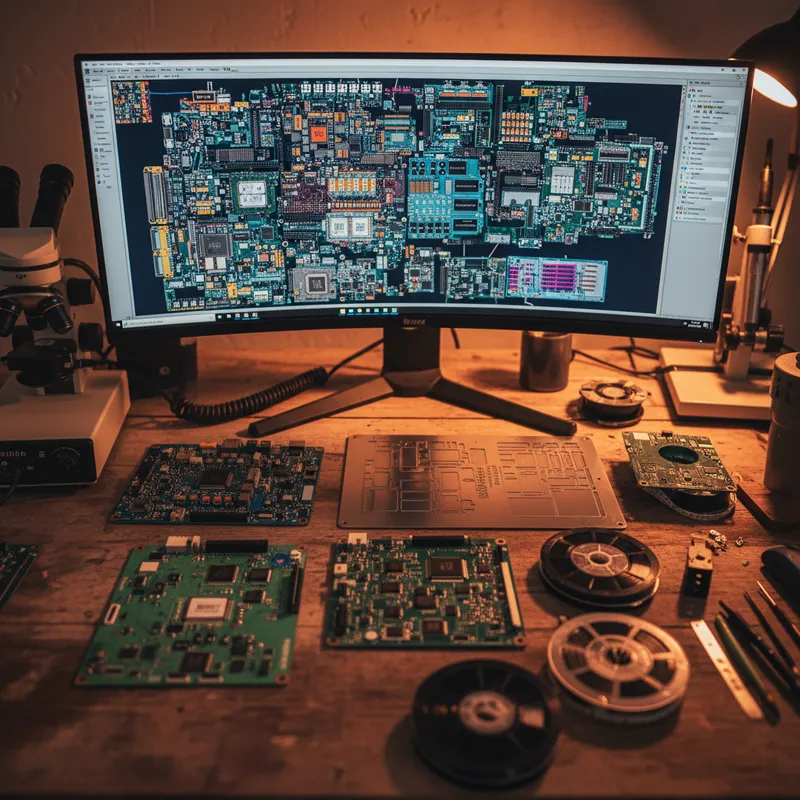
The Field Failure Problem
Field failures in electronic systems are expensive. The direct costs, warranty repairs, spare parts, service engineer travel, customer downtime, are quantifiable. The indirect costs, reputation damage, lost follow-on orders, delay in qualification programs, are harder to measure but often larger.
For Indian electronics manufacturers competing for defense contracts, rail signaling programs, or medical device approvals, a pattern of field failures can disqualify a company from future procurements.
The uncomfortable truth about most field failures is that they are not caused by component defects or manufacturing errors. They are caused by insufficient design margin. The component is used within its absolute maximum ratings according to the datasheet, but the actual operating stress, accounting for worst-case input conditions, maximum ambient temperature, component tolerance stacking, and aging effects, exceeds the margin that the component needs for long-term reliable operation.
Design for Reliability (DfR) is the systematic practice of verifying design margin and identifying reliability risks at the earliest possible stage of the design process, when the cost of correction is lowest.
The DfR Workflow
Step 1: Stress Analysis at the Schematic Level
Before PCB layout begins, every component in the circuit should have its actual operating stress calculated under worst-case conditions. This means determining the voltage across every capacitor, the current through every resistor, the power dissipation in every semiconductor, and the junction temperature of every active device, not at nominal conditions, but at the worst-case combination of input voltage tolerance, load variation, and ambient temperature.
This analysis requires knowing the interface conditions, the voltage and current characteristics at every connector, defined by the Interface Control Document (ICD). BQR’s fiXtress imports schematic data from standard EDA tools and uses the ICD to perform a complete stress analysis, calculating the actual stress on every component under the defined operating conditions.
Step 2: Derating Verification
Once the actual stress is known, it is compared against the applicable derating standard. Derating standards specify the maximum allowed percentage of a component’s rated parameter that may be applied in a given application environment. For example, a typical military derating standard might limit a capacitor’s applied voltage to 60% of its rated voltage, or limit a semiconductor’s junction temperature to 110 degrees C below its maximum rated temperature.
Common derating standards used in Indian programs include MIL-STD-975 (NASA), ECSS-Q-ST-30-11C (ESA), and various customer-specific standards that defense PSUs and private defense manufacturers maintain. fiXtress supports all standard derating tables and allows custom standards to be defined.
Every violation, every component where the actual stress exceeds the derated limit, is a potential reliability risk. fiXtress generates a Pareto chart ranking violations by severity, enabling the design team to address the most critical violations first.
Step 3: MTBF Prediction Under Actual Stress
With the stress analysis complete, fiXtress computes the MTBF prediction using the actual calculated stress values rather than assumed nominal values. This produces a realistic prediction that reflects the design’s actual margin, not an optimistic prediction based on datasheet typical values.
The prediction result identifies the components that contribute most to the system failure rate. In a typical electronic assembly, a small number of components, typically power semiconductors, electrolytic capacitors, and high-power resistors, dominate the system failure rate. Improving the margin on these critical components (by selecting higher-rated parts, adding heatsinks, or redesigning the circuit to reduce stress) provides the greatest reliability improvement per engineering dollar spent.
Step 4: System-Level RAMS Analysis
The component-level reliability data from fiXtress feeds into BQR’s CARE platform for system-level analysis. CARE builds the FMEA/FMECA to identify failure modes and their effects, constructs fault trees to model safety-critical hazards, and assembles reliability block diagrams to calculate system availability.
This system-level analysis answers the questions that matter to the customer: What is the system MTBF? What is the steady-state availability? What are the single-point failures? Which failure modes are safety-critical? What is the fault detection coverage?
Step 5: Maintenance Strategy Optimization
For systems entering operational service, the reliability data from CARE feeds into apmOptimizer for maintenance strategy optimization. apmOptimizer determines the optimal preventive maintenance intervals, spare parts stocking levels, and repair-versus-replace decisions that minimize lifecycle cost while maintaining the required availability.
The Economic Argument for DfR
The cost of DfR tools and the engineering time to run the analysis are trivial compared to the cost of field failures. A single field failure investigation, root cause analysis, corrective action design, requalification testing, retrofit of fielded units, typically costs lakhs of rupees and months of schedule. A systematic DfR program that catches the same defect at the schematic level costs hours of engineering time and a component change on the bill of materials.
For organizations pursuing ISO 9001, AS9100, or IATF 16949 certification, a documented DfR process provides objective evidence of design validation that auditors expect to see. BQR’s integrated toolset generates audit-ready reports that trace from component stress through derating verification to MTBF prediction and system-level safety analysis.
Building DfR Capability in India
The reliability engineering discipline in India is growing rapidly, driven by defense modernization programs, automotive electronics localization, and the expansion of Indian companies into regulated export markets. But many organizations are still building their reliability engineering teams and processes from the ground up. They need tools that are powerful enough for serious engineering work but accessible enough for engineers who are learning reliability methodology alongside their design responsibilities.
BQR’s suite, fiXtress for design-phase reliability, CARE for system-level RAMS, apmOptimizer for operational maintenance, provides that combination of capability and accessibility. The tools share a common interface philosophy, a common component database, and integrated data flow that eliminates manual data transfer between analysis phases.
Why Buy BQR From GSAS
GSAS is an authorized engineering partner in India, providing the complete reliability software suite with INR invoicing, installation, training, and application support from offices in Bengaluru, Hyderabad, Chennai, Pune, Mumbai, and Delhi NCR.
Contact sales@gsasindia.com or call +91 80 6590 1783 to discuss your reliability engineering requirements.
Also appears in:
Interested in BQR tools?
Talk to our application engineers for personalized tool recommendations.
More from BQR
View all →
apmOptimizer Deep Dive: How BQR's Asset Maintenance Software Cuts Lifecycle Costs
5 Apr · 7 min

BQR CARE Deep Dive: Unified RAMS Analysis for Safety-Critical Systems
5 Apr · 7 min
fiXtress Deep Dive: PCB Reliability Prediction and Automated Schematic Review
5 Apr · 7 min
FMEA and FMECA for Indian Defense Programs: A Practical Guide
5 Apr · 7 min

Emulating Processor Power for Thermal Testing: Why Constant Power
7 Oct · 7 min

CRPS and Rack Power Supply Testing: The Six Tests That Matter
7 Oct · 7 min


