The GW Instek Oscilloscope Lineup
GW Instek offers oscilloscopes from 70 MHz entry-level models to 1 GHz high-performance instruments, plus specialized mixed-domain and mixed-signal variants. This guide maps each series to the applications and budgets where it fits best.
Entry Level: GDS-912 and GDS-1000B
GDS-912 Series
The GDS-912 is GW Instek’s entry-point oscilloscope, a compact instrument aimed at education, field service, and basic bench troubleshooting. It provides the essential oscilloscope functions (timebase, trigger, cursors, automatic measurements) at the lowest cost point in the lineup.
GDS-1000B Series
The GDS-1000B series steps up to 100 MHz bandwidth with 4-channel input, 1 GSa/s sample rate, and a feature set that covers most general-purpose bench applications. The GDS-1104B (100 MHz, 4-channel) is the most popular model in this series.
Best for: Education labs, electronics repair, general-purpose bench work where 100 MHz bandwidth is sufficient.
Mid-Range: GDS-2000A and GDS-2000E
GDS-2000A Series
The GDS-2000A provides 100-300 MHz bandwidth with 2 GSa/s sample rate and deeper memory (10M points standard). The higher sample rate and memory depth make it suitable for capturing longer time records at full bandwidth, important for debugging serial protocols and intermittent glitches.
GDS-2000E Series
The GDS-2000E is positioned as an economy mid-range oscilloscope with a simplified feature set at a lower price point than the GDS-2000A. It provides adequate performance for production test applications where advanced analysis features are not required.
Best for: R&D bench work, serial protocol debugging, production test stations where 100-300 MHz bandwidth covers the signal frequencies of interest.
High Performance: GDS-3500 and GDS-3000A
GDS-3500 Series
The GDS-3500 is a 500 MHz Visual Persistence Oscilloscope (VPO), it overlays multiple acquisitions on the display to reveal intermittent signal anomalies and jitter characteristics that single-shot acquisitions would miss. The VPO display mode is particularly useful for debugging power supplies (showing switching noise and load transient responses) and characterizing clock jitter.
GDS-3000A Series: Flagship
The GDS-3000A is GW Instek’s flagship oscilloscope: 1 GHz bandwidth, up to 4 channels (GDS-3104A), 5 GSa/s sample rate, and power analysis capability. The GDS-3000A includes built-in power analysis functions, switching loss, harmonics, dI/dt, dV/dt, that are normally add-on software licenses on competing platforms.
Best for: Power electronics design, high-speed digital debugging, EMC pre-compliance, signal integrity analysis.
Specialized Variants
MDO-2000A: Mixed-Domain
The MDO-2000A combines an oscilloscope with a built-in spectrum analyzer, displaying time-domain and frequency-domain views simultaneously. This mixed-domain capability is useful for debugging RF systems, wireless IoT devices, and any design where both time-domain waveforms and frequency-domain spectral content are relevant.
MSO-2000E / MSO-2204EA: Mixed-Signal
The MSO (Mixed-Signal Oscilloscope) variants add 16 digital logic channels to the analog oscilloscope inputs, enabling simultaneous analog and digital signal capture. This is essential for debugging embedded systems where analog signals (power rails, sensor outputs) and digital signals (SPI, I2C, UART) must be correlated in time.
MPO-2000: Python Programmable
The MPO-2000 series supports Python scripting directly on the oscilloscope, users can write Python scripts that run on the instrument, automating measurement sequences, data analysis, and custom display overlays without an external PC. The MPO-2204P (200 MHz, 4-channel) is the primary model.
Best for: Automated test development, custom measurement routines, education (teaching instrument programming alongside electronics).
Selection Matrix
| Application | Bandwidth | Recommended Series |
|---|---|---|
| Education, basic bench | 70-100 MHz | GDS-912, GDS-1000B |
| General R&D bench | 100-300 MHz | GDS-2000A |
| Production test | 100-200 MHz | GDS-2000E |
| Power electronics | 500 MHz-1 GHz | GDS-3500, GDS-3000A |
| RF / wireless debugging | 200 MHz | MDO-2000A |
| Embedded systems | 200 MHz + 16 digital | MSO-2204EA |
| Automated testing / Python | 200 MHz | MPO-2000 |
Choosing Bandwidth
The general rule: the oscilloscope’s bandwidth should be at least 5x the highest fundamental frequency of interest to accurately capture the signal’s shape (including harmonics). For digital signals, use 5x the clock frequency.
- 50 MHz clock → 250 MHz oscilloscope minimum → GDS-2000A or higher
- 100 MHz clock → 500 MHz minimum → GDS-3500 or GDS-3000A
- SMPS switching at 500 kHz → 2.5 MHz minimum (any GW Instek model), but power analysis features favor GDS-3000A
Availability Through GSAS
GSAS Micro Systems provides the full GW Instek oscilloscope range in India as an authorized GW Instek partner for Karnataka, Andhra Pradesh and Telangana. Services include bandwidth selection consultation, probe recommendations, demo units, and after-sales calibration from offices in Bengaluru, Hyderabad, Chennai, Pune, Mumbai, and Delhi NCR.
Also appears in:
Interested in GW Instek tools?
Talk to our application engineers for personalized tool recommendations.
More from GW Instek
View all →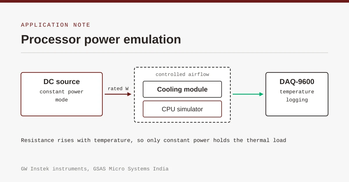
Emulating Processor Power for Thermal Testing: Why Constant Power
7 Oct · 7 min
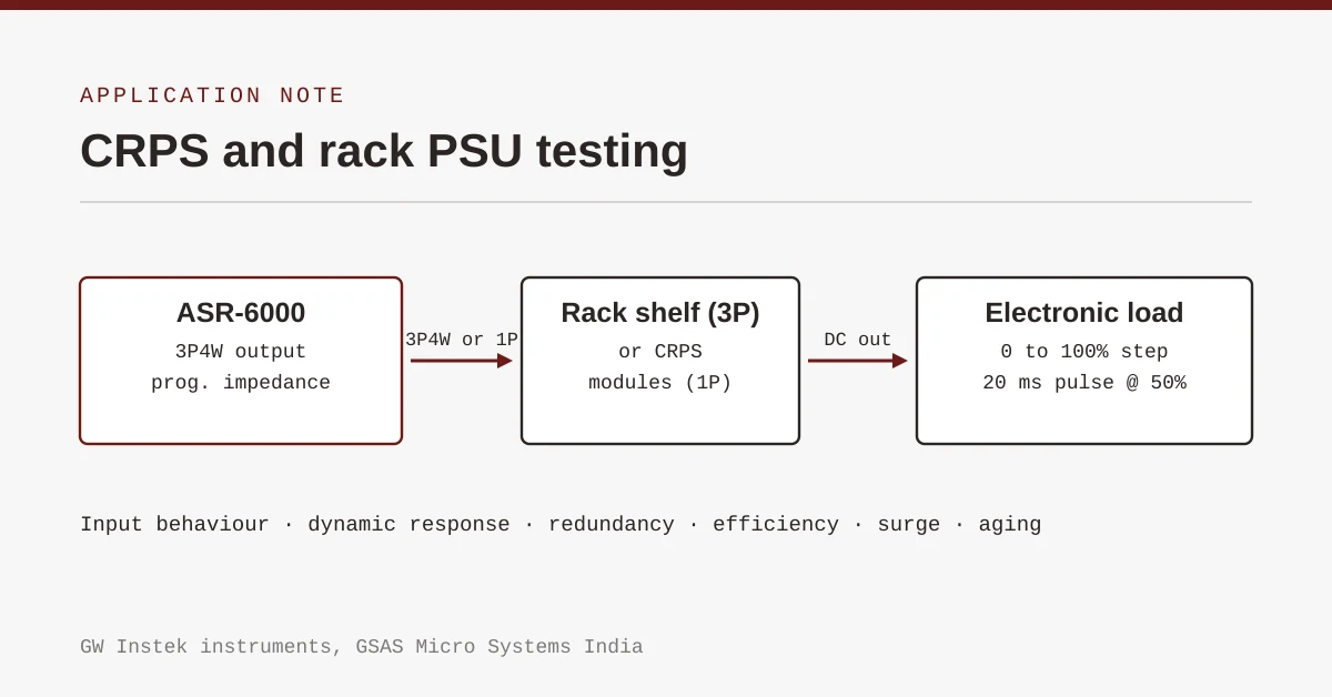
CRPS and Rack Power Supply Testing: The Six Tests That Matter
7 Oct · 7 min
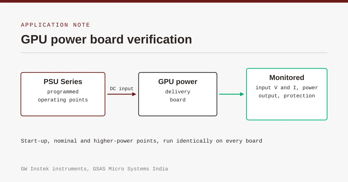
GPU Power Board Testing: DC Input Verification Before Integration
7 Oct · 6 min
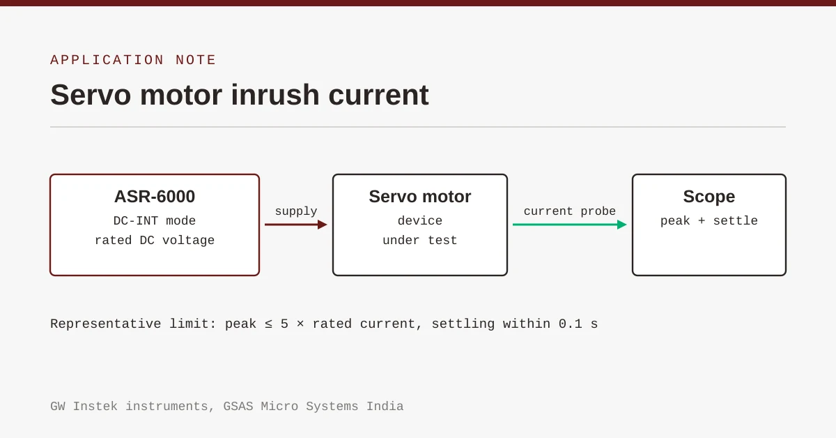
Servo Motor Inrush Current Testing: Method, Limits and Bench
7 Oct · 6 min

HyperLynx 2610: What's New for India's Signal and Power Integrity Teams
4 Nov · 6 min
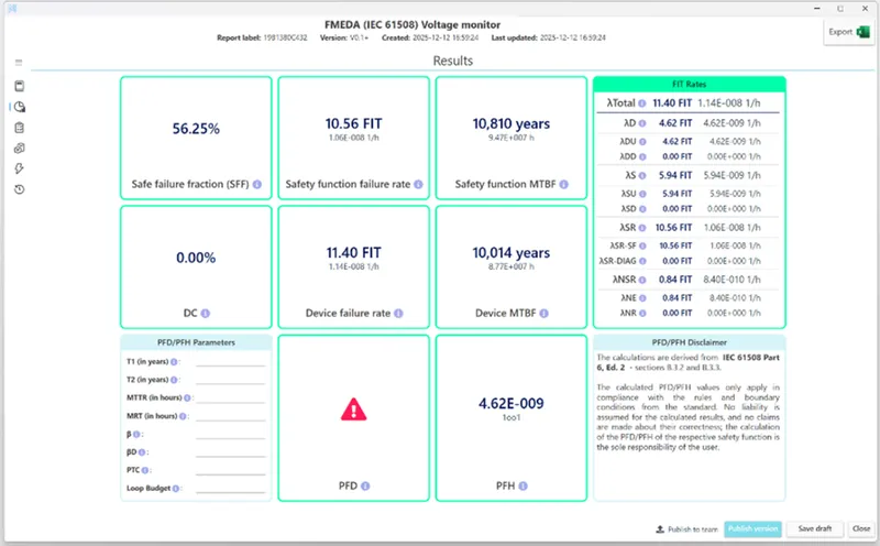
Simulation-Based FMEDA: HyperLynx AMS and Xpedition in the Functional Safety Workflow
4 Nov · 5 min