In short
A motor drive test bench needs a DC bus that supplies the drive and absorbs the energy returned when the motor brakes or an overhauling load drives it. Size the bench from the bus voltage you intend to create and from the braking peak, not the nameplate kilowatts: a drive fed from a 400 V line idles near 565 V.
A drive on a test bench is usually powered at its DC link terminals rather than through its own rectifier. That is where the test engineer gets control: the bus voltage becomes a setting instead of whatever the incoming line happens to deliver, sag and swell can be programmed, and the drive can be exercised at the top and the bottom of its input window without touching the facility supply.
The catch is that a real DC bus is not a one-way street, and a bench that only pushes power is not a model of one. Every drive worth testing sends energy back into its bus at some point, and the bench has to be the thing that takes it.
What Happens Electrically When a Drive Brakes
A motor under braking is a generator. Command a deceleration, or let an overhauling load turn the rotor faster than the commanded speed, and the energy stored in the rotating mass has to go somewhere. The inverter’s switches and their anti-parallel diodes carry it back into the DC link, which physically is a capacitor bank.
Charge pushed into a capacitor raises its voltage, so the bus pumps up. A diode bridge conducts in one direction only, so on a product fed from its own rectifier there is no path back to the line and the bus climbs until something absorbs the energy. In a finished product that something is a brake chopper switching the surplus into a resistor as heat, or an active front end inverting it back onto the incoming line.
On the bench the drive’s own rectifier is out of the circuit, so the instrument on the DC link terminals is the only thing standing between a braking transient and an over-voltage trip. Absorbing regenerated energy is not an optional extra in the bench specification. It is the specification.
The Conventional Bench and Its Three Problems
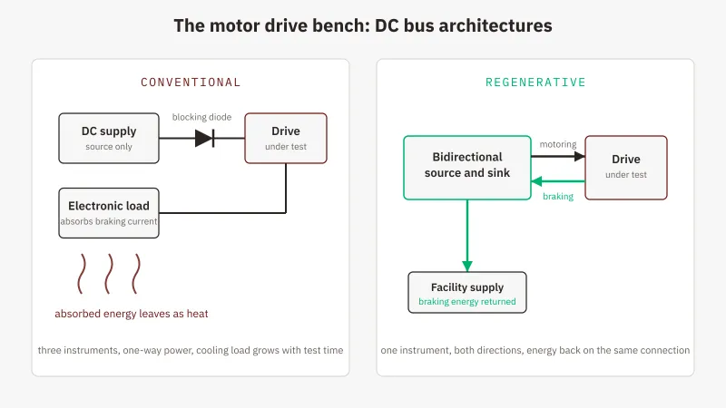
The traditional answer is three parts: a DC power supply for the bus, a series blocking diode so reverse current cannot reach the supply, and a separate electronic load in parallel to consume what comes back. This is the arrangement GW Instek positions the RBS Series against, and it has three characteristic weaknesses.
The blocking diode is in the path all the time. A conducting silicon rectifier drops on the order of a volt, so at a hundred amps that is on the order of a hundred watts turned into heat and taken out of the bus. It also sits between the supply’s regulation point and the drive, so what the supply holds steady is not quite what the drive sees. Remote sensing past the diode recovers the DC accuracy, but the diode still stops conducting the instant the drive tries to push current the other way.
Nothing owns the bus at the crossover. Two instruments means two control loops. The supply regulates while current flows out of it, the load regulates while current flows into it, and around zero current neither is fully in charge. The handover shows up as a dead band, a range of operating points where the bus is held by the drive’s capacitance and by whatever the two loops do at their thresholds. Braking transients are exactly the moment the current crosses zero, so the crossover is where the bench is least well behaved and where the behaviour you came to observe happens.
All the braking energy becomes heat. A dissipative load converts every returned joule into heat inside its chassis, and the room spends more energy removing it. On a duty cycle that brakes every few seconds for hours, that is a thermal load which scales with test duration.
One Instrument on the DC Link Terminals
A regenerative bidirectional DC source removes all three problems by removing two of the three boxes. If the category is new to you, how a regenerative bidirectional DC power supply works covers the architecture: one converter, two directions, absorbed energy converted back to mains-synchronised AC and returned to the facility supply instead of leaving as heat.
For a motor bench the consequence that matters is that voltage programming is common to both directions. The instrument holds the bus at the setpoint and lets the current be whatever the drive demands, positive while the machine motors and negative while it brakes, with no diode in the path and no handover. On the GW Instek RBS Series the load side carries constant-voltage among its modes alongside constant current, power and resistance, and because both directions are one converter, the source-to-sink transition is a control handover measured in milliseconds rather than a rewiring step. GW Instek puts recovery at up to 93% each way, and with it the cooling load stops tracking test duration.
Matching the Instrument to a Drive’s Bus and Braking Peak
Voltage Class Follows the Bus You Intend to Create
Fix the voltage class first, as the selection guide sets out, and work from the bus the bench will actually produce rather than from the drive’s input rating. A six-pulse rectifier on a 400 V three-phase line gives an average DC of roughly 1.35 times the line-to-line voltage under load, close to 540 V, and a capacitor-filtered bus drifts toward the 1.414 times peak, near 565 V, at light load. The idle bus alone rules out the 500 V class.
The next question is what the bench intends to do above that. The 750 V class covers a 400 V-fed drive’s normal operating bus with margin. But brake-chopper thresholds and over-voltage trips on 400 V-class drives commonly sit near 800 V, and a braking test is deliberately trying to reach them; a bench built to exercise those thresholds is creating a voltage the 750 V class cannot hold, and the headroom rule sends it to the 1000 V class. Elsewhere in the range, the 500 V class suits drives fed from a 230 V line and lower-voltage traction buses, and the 100 V class suits 48 V industrial and light-traction buses where current matters more than voltage.
The Current Envelope, and Sizing for the Braking Peak
At any operating point the current you get is whichever is lower, the rated current or the rated power over the voltage you are working at, a rule the selection guide linked above works through. On this bench the number that matters: a 20 kW model in the 750 V class is rated ±120 A, but at a 565 V bus 20 kW supports around 35 A, and the full ±120 A only exists at or below 167 V, far under any 400 V-drive bus. A requirement written as a number of amps means nothing until a bus voltage is attached to it.
Then size for the peak rather than the average. Braking a high-inertia load quickly returns more power for a few seconds than the machine draws while running, and that transient is what the sink has to survive. Either buy an envelope that covers it, or program the deceleration ramp so the peak stays inside the envelope you have.
Cycle Profiles, Precharge and the Protection That Matters
Motor-drive work is profile work, not steady state, and the profile belongs in the instrument rather than in a technician’s hands. The RBS holds up to 50 stored sequences, 20 steps each, with the level, mode, timing and loop count set per step, which covers a realistic routine: ramp the bus up rather than connecting a stiff source cold to a large capacitor bank, hold at nominal through an acceleration, step to the bottom of the drive’s input window and back to the top, dwell through a braking segment, and loop as many times as the qualification demands.
Two more details earn their place. Output resistance can be dialled in from 0 Ohm up to the class maximum, which lets the bus behave like a real feed through a rectifier and cable rather than an ideal stiff source. And over-voltage protection, settable from 0 to 110% of full scale, matters most on this bench, because a braking transient is by definition a bus over-voltage event and you want the limit enforced by the instrument rather than discovered by the drive. Over-current, over-temperature, remote-sense reverse and input over and under-voltage protection complete the set.
One caveat on transient response. The published 2 ms figure carries a footnote: a 50% to 100% or 100% to 50% load step, recovering to within 0.75% of rating. That is a load step, not a source-to-sink reversal, so if the reversal rate is critical to your profile, ask for the conditions behind that number.
When a Dissipative Load Still Belongs on the Motor Bench
Not every motor bench should be rebuilt around regeneration. If braking events are short and infrequent, the energy recovered over a year will not pay for the architecture, and the sizing arithmetic is in regenerative electronic load vs traditional. Protection work is the clearer case: fuse and breaker coordination on the drive’s input side still wants a dissipative platform, and plenty of motor labs keep a GW Instek AEL-5000 Series load alongside the bidirectional source and choose per test.
Two adjacent jobs stay on their own benches: instrumenting the switching waveforms at the inverter is oscilloscope and probe work, and testing the machine’s windings is a different instrument again. The power architecture covered here is a separate question from both.
Where GSAS Fits
GSAS Micro Systems is an engineering partner for GW Instek in India, and the motor-bench conversation worth having happens before anything is quoted: the bus voltage your bench will actually create, the braking peak against the deceleration ramp, and whether your three-phase supply matches the instrument’s input window. If the duty cycle does not justify regenerative hardware, that is better heard at the specification stage than after commissioning.
Per-model ratings sit under RBS Series 750 V and 1000 V class ratings and India pricing. Demos, evaluation units, installation, calibration and after-sales run from our offices in Bengaluru, Hyderabad, Chennai, Pune, Mumbai and Delhi NCR.
Send the drive’s DC-link rating, the inertia you are decelerating and the ramp time with a request for quote, and the reply will size the sink envelope against the braking peak before naming a model.
Also appears in:
Interested in GW Instek tools?
Talk to our application engineers for personalized tool recommendations.
More from GW Instek
View all →
Emulating Processor Power for Thermal Testing: Why Constant Power
7 Oct · 7 min

CRPS and Rack Power Supply Testing: The Six Tests That Matter
7 Oct · 7 min

GPU Power Board Testing: DC Input Verification Before Integration
7 Oct · 6 min
Servo Motor Inrush Current Testing: Method, Limits and Bench
7 Oct · 6 min

SuperTest Van Gogh 6.0: C23, C++23 and the C++20 Modules Gap
6 Oct · 7 min

AI Inside the Engineering Process: What Is Worth Automating, and What Still Needs an Engineer
21 Sept · 11 min