
In short
A regenerative bidirectional DC power supply is one instrument that both sources power to a device under test and sinks power from it, and that converts the energy it absorbs back to AC synchronised with the mains, feeding it to the facility grid for other loads to consume instead of dissipating it as heat in a resistor bank.
Three names circulate for what looks like one instrument: bidirectional DC power supply, regenerative DC power supply, four-quadrant DC power supply. They are not interchangeable, and the difference decides whether the box saves money every hour it runs or only saves a few rack units. This article takes the category first, then uses the GW Instek RBS Series as the worked example.
What a Regenerative Bidirectional DC Power Supply Is
Three properties have to hold at once: the terminals must source, the same terminals must sink, and the absorbed energy must leave the instrument as mains-synchronised AC rather than heat. Drop any one and you are looking at a different category of instrument.
Bidirectional is about the direction of current at the terminals: the instrument can push current into the device under test and pull current out of it, under the same voltage programming, with no rewiring in between.
Regenerative is about the fate of the energy that comes out. A dissipative sink turns it into heat inside the chassis, and the heat then has to leave the room. A regenerative sink turns it back into mains-frequency AC and puts it on the building’s distribution.
A supply can be bidirectional without being regenerative. It cannot be regenerative without being bidirectional, because there is nothing to regenerate unless it is absorbing. Look for both words on a datasheet.
How the Architecture Works
Both functions live in one chassis, sharing the output terminals, the programming and the protection envelope. Sourcing and sinking are not two instruments behind a relay, they are two directions of one converter, so the transition takes milliseconds and needs no rewiring.
The regeneration path is easiest to picture by analogy with a grid-tied solar inverter, which produces AC synchronised in frequency and phase with the mains, so what it injects is indistinguishable from utility energy to everything else on that distribution. A regenerative DC supply does the same with a different DC source: the device under test. Energy returns on the same three-phase connection that feeds the instrument and is consumed by whatever else draws on that distribution, other test stations, lighting, air conditioning, before any of it reaches the utility meter, provided that local load exceeds what is being returned.
None of it is lossless. GW Instek rates the RBS Series at up to 93% efficiency in both the sink and source directions, with a typical power factor of 0.99. Of every 100 kWh a dissipative load would have turned into heat, up to 93 can come back as usable AC at that quoted ceiling, with the realised fraction depending on operating point. Two lines in the facility budget move at once: the meter records the difference between what the test draws and what it returns rather than the full absorbed load, and the air conditioning is no longer run against the full absorbed power as continuous waste heat per station, a live constraint in an Indian lab where HVAC carries close to full-year duty.
Two Quadrants, Not Four: What Replaces the Supply-Plus-Load Bench
If your mental model of DC testing is a supply on one side and an electronic load on the other, this architecture is a subtraction rather than a new feature.
The classic bench needs three things: a programmable supply to set the device’s rail, a blocking diode between supply and device because a conventional output stage cannot absorb reverse current and will fault or fail when the device pushes energy back, and a separate electronic load on the same node to take that reverse current and burn it off. Each of the three costs something that is not on the price list. The diode drops voltage and puts a discontinuity exactly where the device crosses from drawing to delivering. The handover between supply and load leaves a dead band around zero current, and that band is where converter and BMS bugs like to hide.
Folding both into one chassis removes all three: the device faces one instrument across the whole current range, positive and negative current become one programmed quantity with a sign, and one sequence controls both directions.
One caution on terminology: bidirectional current at a positive output voltage covers two quadrants of the voltage-current plane, while a genuinely four-quadrant instrument also reverses output polarity. Most of what is specified for EV and energy-storage work, the RBS Series included, is the bidirectional-current form: a source range from 0 V up to the model’s rated voltage, sink operation from a floor of 5 V on the 100 V class and 10 V on every other class, and current of either sign.
Where It Pays
The architecture pays by absorbing energy, not by being present. The saving has two parts, recovered energy that offsets the meter and cooling the facility never runs because the heat was never made, and both scale with utilisation: continuous cycling, burn-in and homologation work recover the premium, short intermittent tests do not. The sizing method, worked against a specific station, lives in our comparison of the two load architectures below, and the facility-level case, including what is driving Indian labs toward energy recovery, in why power labs are moving to energy recovery.
One workload class stands apart: genuinely bidirectional devices. On-board chargers, traction DC-DC converters and grid-tied storage interfaces need both directions of power flow whatever energy costs. For them the architecture is a functional requirement, and regeneration is a bonus.
What the Architecture Looks Like in a Shipping Instrument
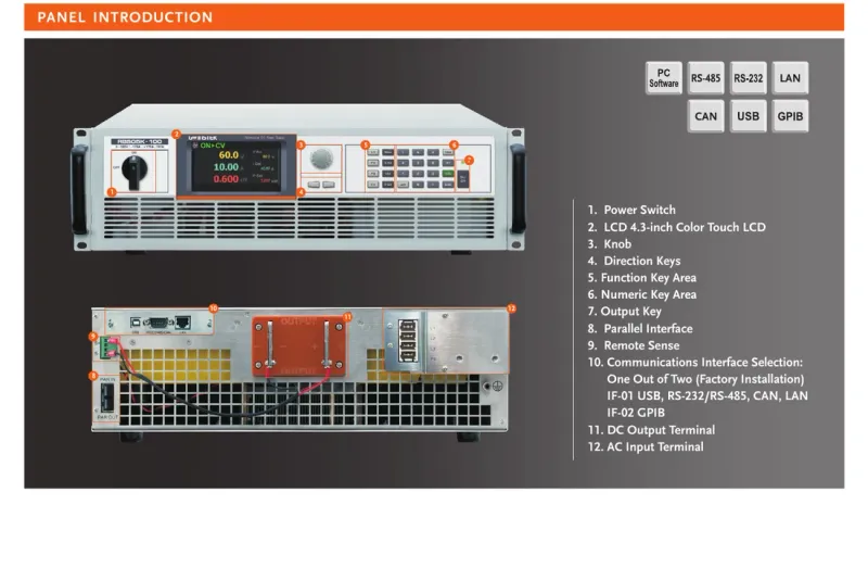
GW Instek’s implementation is the RBS Series: twenty models on one 3U, 19-inch platform, spanning 5 kW to 30 kW across six voltage classes from 100 V to 2250 V. Current is bidirectional, the same magnitude sourcing or sinking, and the single-unit ceiling is ±510 A on the 15 kW, 100 V model. Local operation is through a 4.3-inch colour touch panel. Per-model ratings, current by voltage class, input current and weight are on the RBS Series specifications, model ratings and India pricing page, where a shortlist should start.
Transient response is specified at 2 ms, and the condition attached is worth reading. GW Instek defines it as a load step of 50% to 100% or 100% to 50% of rating, with the output voltage returning to within 0.75% of rating: a step between two substantial load levels, not zero to full, and a settling band of 0.75%, not zero. Compare it against another instrument’s transient figure only after confirming the same step and the same band.
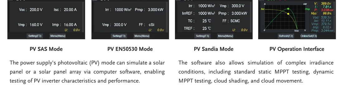
Solar Array Simulation is standard, but only on models rated 500 V and above, carrying PV SAS, EN50530, Sandia, SAS2 and user-defined I-V profiles for static and dynamic MPPT work including cloud shading and movement; solar array simulation for PV inverter MPPT testing covers that workload. If PV inverter testing is in scope at all, that footnote removes the entire 100 V class from the shortlist.
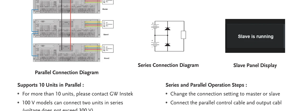
Remote control is one of two factory-installed cards, not both: either the all-in-one interface with USB, RS-232/RS-485, CAN and LAN, or GPIB. The choice is made at order time, so a lab standardised on GPIB racks should say so on the purchase order. For power beyond one chassis, up to ten units of the same model run in master-slave parallel; each model’s system ceiling is ten times its own rating, so ten of the 30 kW models reach 300 kW.
Battery Simulation Without a Physical Pack
Two different things on this instrument get called battery testing, and they run in opposite directions.
The first is battery simulation. The RBS carries eight fixed chemistry models plus one user-defined model: lithium manganate (LMO), lithium cobalt oxide (LCO), lithium iron phosphate (LFP), ternary lithium (NCM), lithium titanate (LTO), lead-acid (Pb), nickel-metal hydride (NiMH) and nickel-cadmium (NiCd). It reproduces the selected chemistry’s voltage-current characteristic and its state-of-charge behaviour, so the terminals behave like a pack sitting at a programmed SOC rather than like a stiff supply holding a fixed voltage.
That distinction is the whole value of the function. A battery management system, a charger or a traction inverter reads its input as a battery: voltage sags as it draws, recovers when it stops, and moves along the chemistry’s characteristic as charge accumulates or drains. Feed the same device from an ordinary supply and it sees none of that, so every code path that responds to pack behaviour goes unexercised. With simulation, a BMS can be qualified against a low state of charge, a high one, or a chemistry the programme has not yet procured, repeatably and with no physical pack on the bench: no cell inventory, no thermal risk, and no waiting for a pack to reach the state a test needs.
The second direction is real-pack cycling. A dedicated charge and discharge mode connects to an actual battery-type load and runs full cycles with the protection envelope active, covering over-voltage, over-current, over-temperature and input over and under-voltage. The discharge half of every cycle is absorbed energy, and on a dissipative bench that is the half you pay for twice, once at the meter and again at the air conditioner. Returning it to the distribution is what makes round-the-clock cycle testing a standing commitment rather than a line item somebody queries every quarter.
The two complement each other: simulation qualifies the BMS and charging logic early, before cells are available, and real-pack cycling validates against the physical article later; regenerative DC testing for EV validation maps both onto Indian EV programmes. The sequence engine, up to 50 stored sequences of 20 steps with voltage, current or power, mode, dwell time, loop and ramp set per step, turns either into an unattended overnight routine. For the simulator-versus-emulator question and the battery-specific specification checks, see battery simulator vs battery emulator.
Where It Does Not Pay
There are workloads where a dissipative load is the correct instrument and a regenerative one is money spent on physics you are not using. Bench-scale, sub-kilowatt work and stations that run at full power for minutes a day never accumulate enough absorbed energy to grow into the price difference. A device that never delivers power leaves half of a bidirectional instrument idle. A site with restrictions on net energy export needs enough local base load to absorb what comes back on the supply connection. And some modes exist only on dissipative platforms: Turbo mode and AC rectifier load mode, used for UPS, inverter and breaker work, are the territory of instruments like the GW Instek AEL-5000 Series, whose non-regenerative architecture is a design choice, not a shortcoming.
For the two architectures side by side, with the sizing question worked through against a specific workload, see Regenerative Electronic Load vs Traditional.
Where GSAS Fits
GSAS Micro Systems is an engineering partner for GW Instek in India, and the part of this decision we are most useful for sits before the purchase order: matching a voltage and current envelope to a device still on the drawing board, working out whether one 15 kW chassis now or two smaller units in parallel later suits a programme that will grow, and running the payback arithmetic with your tariff and duty cycle, including when the numbers do not support the regenerative option. Our application engineering, calibration and after-sales support work out of offices in Bengaluru, Hyderabad, Chennai, Pune, Mumbai and Delhi NCR.
If the architecture is settled, how to choose a regenerative bidirectional DC power supply walks the selection criteria in order. Otherwise request a quote or book a demo and we will start from your test profile rather than our catalogue.
Also appears in:
Interested in GW Instek tools?
Talk to our application engineers for personalized tool recommendations.
More from GW Instek
View all →
Emulating Processor Power for Thermal Testing: Why Constant Power
7 Oct · 7 min

CRPS and Rack Power Supply Testing: The Six Tests That Matter
7 Oct · 7 min

GPU Power Board Testing: DC Input Verification Before Integration
7 Oct · 6 min
Servo Motor Inrush Current Testing: Method, Limits and Bench
7 Oct · 6 min

SuperTest Van Gogh 6.0: C23, C++23 and the C++20 Modules Gap
6 Oct · 7 min

AI Inside the Engineering Process: What Is Worth Automating, and What Still Needs an Engineer
21 Sept · 11 min


