
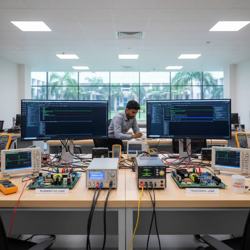
Two Architectures, Two Purposes
A traditional (dissipative) electronic load converts every watt absorbed from the device under test into heat. A bank of MOSFETs or resistive elements dissipates the absorbed energy, and a fan/heatsink, sometimes liquid cooling at high power, removes the heat from the chassis. Architecturally simple, well-understood, and inexpensive at low power.
A regenerative load converts the absorbed DC energy back to AC synchronised with the facility’s mains and feeds it into the building’s electrical grid. Instead of becoming heat, the absorbed energy is consumed by other loads on the same distribution.
The two architectures coexist in modern labs because they answer different questions. Dissipative loads are about loading the DUT precisely. Regenerative loads are about loading the DUT precisely and not paying for the absorbed energy in electricity and HVAC.
When Regenerative Makes Sense
- Continuous high-power operation. Battery cycling, EV charger qualification, solar-inverter production test, and grid-tied energy-storage testing routinely run at tens of kilowatts for many hours per cycle. The energy and thermal cost dominates station economics here.
- Long duty cycles. Burn-in racks running 24–72 hours, accelerated life testing, and continuous AIS 156 / AIS 038 cycle work all benefit.
- Multiple test stations. Recovered energy from one regenerative load is consumed by other loads on the same distribution, including other test stations, lighting, and HVAC. The net facility draw drops.
- Thermal-constrained labs. Avoiding several kW of waste heat per station reduces both the air-conditioning capital expenditure and the operating cost, particularly visible in Indian climates where ambient temperatures routinely exceed 35 °C and HVAC sees full-year duty.
- Bidirectional workloads. EV on-board chargers, traction-drive DC-DC converters, and bidirectional energy-storage interfaces require both source and sink behaviour. A regenerative bidirectional source covers both in one chassis.
When Dissipative Loads Are the Right Tool
- Bench-scale and characterisation testing. Below roughly 1–2 kW the energy and cooling spend is small enough that the regenerative premium does not pay back over a reasonable horizon.
- Intermittent or burst-mode testing. Short bursts at full power followed by long idle periods accumulate little energy, regardless of how high the peak is.
- Specialised modes a regenerative load does not offer. AC rectifier load mode, fuse and breaker trip testing, transient pulse loading at multiples of nameplate, these are dissipative-load territory, addressed by platforms like the GW Instek AEL-5000.
- Budget-constrained programmes where utilisation is uncertain. A dissipative load is the right starting point if the test workload is still being defined; regenerative can be added later for the high-utilisation stations that emerge.
- Facilities where utility regulations restrict net energy injection. A regenerative load in this case has to operate in a closed-loop or energy-circulating mode, which adds system-design constraints.
Sizing the Decision
Three numbers drive the answer for any specific test station:
- Average loading power × hours per day × working days per year: gives the annual absorbed energy in kWh.
- Industrial electricity tariff in your state and demand category: gives the direct annual energy cost of dissipative loading.
- Cooling offset: every kW of heat not generated avoids a fraction of a kW of HVAC input power (the fraction depends on the air-conditioning system’s coefficient of performance).
The price delta between a comparable dissipative and regenerative platform is then a question of payback period: divide the annual avoided cost (energy + cooling) into the price delta. Above a certain power and duty cycle, the period collapses to a couple of years; below it, the period exceeds the equipment’s economic life.
This calculation, run with the buyer’s actual numbers, is the right way to make the call, not a rule of thumb in either direction. The facility-level view of the same decision, cooling, station density and what is driving Indian labs toward energy recovery, is in why power labs are moving to energy recovery.
GW Instek Lineup
GW Instek’s portfolio covers both architectures:
- RBS Series: regenerative bidirectional DC source-and-sink. 5 kW to 30 kW chassis, voltage models from 100 V to 2250 V, up to 510 A. Bidirectional source and sink with grid energy recovery, eight built-in battery chemistry models, and EN50530 and Sandia PV simulation on models rated 500 V and above. Built for EV battery validation, energy-storage qualification, and bidirectional-converter testing.
- PEL-5000G: high-power DC electronic load with Turbo Mode (1.5× current/power for transient peaks). Three voltage range families (150 V / 600 V / 1200 V), up to 6 kW per module and 48 kW in 8-unit master-slave parallel. Built for power-supply, telecom-rectifier, and battery-discharge characterisation.
- AEL-5000: programmable AC/DC electronic load with Turbo Mode and AC Rectifier Load Mode. 1.875–22.5 kW per unit, parallel to 540 kW (3ϕ). Built for UPS, inverter, fuse, and circuit-breaker qualification.
Buying GW Instek Loads in India
GSAS Micro Systems is an authorized partner in India and supplies the full electronic-load and bidirectional-source portfolio with INR invoicing and application-engineering support from offices in Bengaluru, Hyderabad, Chennai, Pune, Mumbai, and Delhi NCR. Contact sales@gsasindia.com for load-architecture sizing, demo unit access, and parallel-system configuration guidance.
Also appears in:
Interested in GW Instek tools?
Talk to our application engineers for personalized tool recommendations.
More from GW Instek
View all →
Emulating Processor Power for Thermal Testing: Why Constant Power
7 Oct · 7 min

CRPS and Rack Power Supply Testing: The Six Tests That Matter
7 Oct · 7 min

GPU Power Board Testing: DC Input Verification Before Integration
7 Oct · 6 min
Servo Motor Inrush Current Testing: Method, Limits and Bench
7 Oct · 6 min

SuperTest Van Gogh 6.0: C23, C++23 and the C++20 Modules Gap
6 Oct · 7 min

AI Inside the Engineering Process: What Is Worth Automating, and What Still Needs an Engineer
21 Sept · 11 min
