In short
A battery simulator is bench hardware, not modelling software: a programmable DC instrument whose terminals reproduce a chemistry's voltage-current characteristic and state-of-charge behaviour, sourcing and sinking current so a battery management system or charger connected to it responds as it would to a real pack.
A battery simulator, in the sense this article uses the term, is a piece of bench hardware. It is a programmable DC instrument whose output terminals behave like a battery pack, so that a battery management system, an on-board charger or a traction inverter wired to it responds the way it would to real cells. Instruments in this class are rack hardware with a protection envelope, and the higher-power ones draw a three-phase supply.
That needs saying at the top, because the phrase is shared with something else entirely. If what you are looking for is a way to model cell electrochemistry, fit an equivalent-circuit model, or run pack thermal analysis, that work belongs in a modelling environment on a workstation and nothing below will help you. This page is about the box on the bench, what it has to do electrically, and how to specify one.
Simulator or Emulator: A Distinction Nobody Standardised
Search results and datasheets carry both words, often for the same function. It is worth being honest about what separates them, which is less than the vocabulary suggests: no standard we could find defines either term for this class of instrument, and vendors use the two interchangeably.
A working distinction some engineers draw is that simulation computes terminal behaviour from a chemistry model, while emulation reproduces the behaviour of a specific measured pack. It is a reasonable mental split, and it does not survive contact with real product literature, where the same function appears under either name depending on who wrote the page. The nearest thing to a consistent usage is capability-based: an instrument earns either name when it both sources and sinks current and models internal resistance and state of charge, which is the sense our EV charger bench guide uses when it separates a true emulator from a supply pinned at a pack voltage.
So treat the label as a search term and specify against a capability list. Five things decide whether an instrument is useful for battery work, and none of them is the word on the front panel:
- Chemistry models. Which chemistries are built in, and is there a user-defined model for one that is not?
- State-of-charge programmability. Can you set the pack to a state of charge and have the terminals sit where that chemistry would sit, or does SOC only move as a by-product of a running test?
- Sink capability. A battery absorbs charge current. An instrument that only sources cannot pretend to be one for the charging half of any test.
- Transition behaviour. How the instrument crosses from delivering current to accepting it, and how fast, because that crossing is where charger and BMS bugs live.
- Protection. What guards the device under test, and the instrument, when a fault-injection test does exactly what it was written to do.
Why a Plain DC Supply Fails BMS Work
The usual substitute for a battery simulator is a bench supply set to the pack’s nominal voltage. It energises the board, and that is roughly where its usefulness ends.
A stiff supply holds voltage. A battery does not. Its terminal voltage sags under load in proportion to internal resistance, recovers when the load steps away, and moves along the chemistry’s characteristic as charge accumulates or drains. Every one of those behaviours is an input the management system is written to respond to, and a fixed-voltage supply provides none of them.
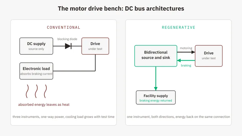
Work through what that costs in coverage. The terminal voltage never moves with charge, so the open-circuit-voltage correction has nothing to correct against and coulomb counting is never held to account by a converging reference. The programmable, state-of-charge-dependent resistance drop that firmware sanity-checks a measurement against never appears, only the fixed drop of cables and contacts, so the code that reacts to an implausible reading is never entered. Low-SOC derating and cutoff paths sit untouched because the supply will happily hold nominal voltage until somebody switches it off. And the moment a device under test tries to push current back, an ordinary supply cannot accept it: the output rises, a protection trips, or a blocking diode you added to prevent exactly that turns the test into something that no longer resembles a pack. Charge-side behaviour compounds it: termination logic waits for a current taper that only an instrument actually absorbing charge current can present. (A deliberately charge-only bench is the honest exception: where the device never regenerates, a source-only supply behind a blocking diode remains a legitimate architecture.)
None of this shows up as a failure. It shows up as a test that passes without having tested anything, which is worse.
What the Hardware Has to Do at Pack Level
Working backwards from that, the requirements are specific.
Current in both directions. The instrument must source during discharge simulation and sink during charge simulation, under one voltage programme, with no rewiring between the two. Practically that means the source and sink halves are two directions of one converter rather than two instruments behind a relay: the crossing becomes a control transition measured in milliseconds instead of a rewiring step, and how cleanly the instrument behaves around zero current is a question worth asking any vendor, because that region is where converter and BMS defects hide.
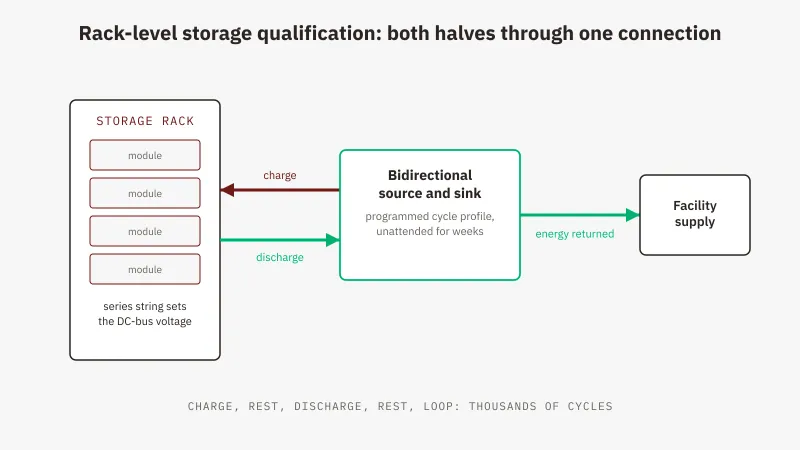
A destination for absorbed energy. Every ampere the instrument accepts arrives as energy that has to go somewhere: heat inside the chassis on a dissipative platform, or mains-synchronised AC returned to the facility distribution on a regenerative one. For short tests that is an accounting detail. For pack cycling measured in days it decides both the electricity bill and the cooling load, which is covered in our piece on how a regenerative bidirectional DC power supply works.
A protection envelope you can aim tests at. Fault injection means deliberately driving conditions the instrument has to survive, so over-voltage and over-current limits need to be settable rather than fixed, with over-temperature, remote-sense reverse protection and input-side protection behind them.
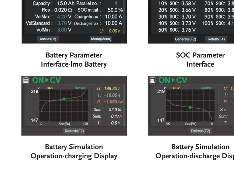
The GW Instek RBS Series is a useful worked example because battery simulation is a standard function on it rather than an option. It carries eight built-in chemistry models, lithium manganate (LMO), lithium cobalt oxide (LCO), lithium iron phosphate (LFP), ternary lithium (NCM), lithium titanate (LTO), lead-acid (Pb), nickel-metal hydride (NiMH) and nickel-cadmium (NiCd), plus one user-defined model, with a state-of-charge parameter setting and charge and discharge displays. Alongside simulation there is a dedicated charge and discharge mode for connecting to a physical battery-type load. Protection covers over-voltage and over-current, each settable across 0 to 110% of full scale, plus over-temperature, remote-sense reverse and input over and under-voltage. The internal-resistance argument above also has a direct answer here: DC output resistance is programmable from 0 Ohm up to a per-class maximum, so the sag a management system sanity-checks against is itself a settable parameter. GW Instek rates energy recovery at up to 93% in both directions, so absorbed energy returns to the AC supply rather than being dissipated. The sequence engine stores up to 50 sequences of 20 steps, which is what turns a cycling profile into an unattended overnight run.
Per-model ratings sit on the RBS Series model ratings, chemistry models and India pricing page.
Simulated Pack or Real Pack: When Each Is Right
These are not competing answers. They are two phases of the same programme, and the instrument that does one usually does the other.
Simulation belongs early. A BMS team can start before a single cell has been procured, hold the pack at a low state of charge for as long as a test needs rather than waiting hours to discharge into one, and switch chemistry between runs to check that the same firmware behaves on a chemistry the programme has not committed to yet. Repeatability is the quiet advantage: a simulated pack starts every run in an identical state, so a defect that appears on the third run is a defect and not a pack that drifted.
Fault injection is where the case becomes hard to argue with. Cell over-voltage, cell under-voltage and over-current conditions all need to be driven deliberately to prove the management system detects them, opens contactors and reports correctly. Driving them into a real pack means creating the abuse condition on cells you then cannot trust and may not be able to keep. Driving them into a simulated pack is a parameter change, repeatable, with the protection envelope active on both sides.
Real packs come later, and they still come. A pack-terminal instrument presents one pair of terminals, so cell-level balancing across individual taps, genuine thermal behaviour and everything that only appears with age belongs to the physical article. That is what the dedicated charge and discharge mode is for, and it is where regeneration earns its place: every discharge in a validation campaign of thousands of cycles arrives as energy the instrument has to absorb. The way both phases map onto Indian EV programmes is worked through in regenerative DC testing for EV validation.
Specifying One: The Battery-Specific Checks
The general selection order, voltage class first with headroom, then the current envelope at your working voltage, is worked through in how to choose a regenerative bidirectional DC power supply. Two checks on top of it are battery-specific.
The sink floor, not only the source ceiling. Source ranges usually start at 0 V; sink ranges often do not. On the RBS Series, sink mode reaches down to 5 V on the 100 V class and 10 V on the rest, so a profile that discharges towards zero needs that floor checked before the order rather than after.
The chemistry list against the roadmap, not the project. Whichever chemistry you are shipping today, the instrument will outlive the decision. Check the built-in list, then check whether there is a user-defined model, because that slot is what covers the chemistry nobody has committed to yet.
Where GSAS Fits
GSAS Micro Systems is an engineering partner for GW Instek in India, and on battery work the useful conversation happens before the purchase order. We work through the voltage and current envelope against the pack you are building rather than the one you have, check the sink floor against your discharge profile, confirm the chemistry list covers the roadmap, and say so when the honest answer is that a simpler instrument covers the workload. Application engineering works in your time zone, and calibration and after-sales support run from our offices in Bengaluru, Hyderabad, Chennai, Pune, Mumbai and Delhi NCR.
Send us the pack terminal voltage, the peak current and the profile you intend to run when you request a quote, and the reply will be a sized answer: model, chemistry coverage and interface card against your numbers.
Also appears in:
Interested in GW Instek tools?
Talk to our application engineers for personalized tool recommendations.
More from GW Instek
View all →
Emulating Processor Power for Thermal Testing: Why Constant Power
7 Oct · 7 min

CRPS and Rack Power Supply Testing: The Six Tests That Matter
7 Oct · 7 min

GPU Power Board Testing: DC Input Verification Before Integration
7 Oct · 6 min
Servo Motor Inrush Current Testing: Method, Limits and Bench
7 Oct · 6 min

SuperTest Van Gogh 6.0: C23, C++23 and the C++20 Modules Gap
6 Oct · 7 min

AI Inside the Engineering Process: What Is Worth Automating, and What Still Needs an Engineer
21 Sept · 11 min