
In short
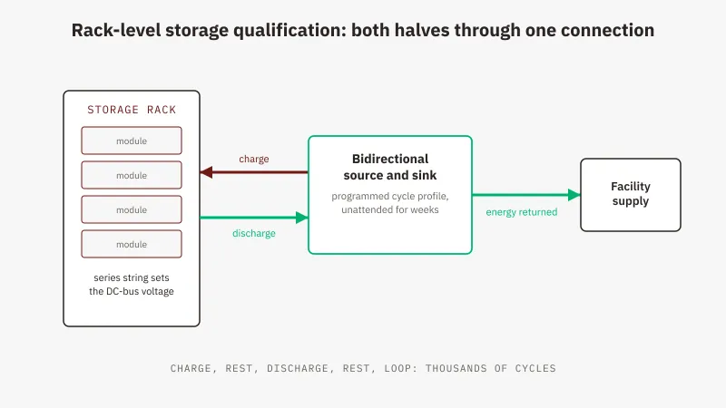
Energy storage qualification is repeated controlled charging and discharging of a rack against a programmed profile, at the rack's DC-bus voltage, for durations measured in weeks. A qualification bench therefore has to source and sink at that voltage through one connection, hold the profile unattended, and absorb the discharge half without dissipating it.
A battery energy storage system is not qualified by measuring it once. It is qualified by running it: charging a rack to the top of its window, discharging it back down, and repeating until enough cycles have accumulated to say something defensible about capacity retention, thermal drift and protection response at the limits. The bench that does this has to source and sink at rack DC-bus voltages, hold a programmed profile with nobody in the room, and keep doing it for weeks. This article covers what that bench looks like, what it cycles, and how it grows. If the source-and-sink architecture underneath it is new to you, start with how a regenerative bidirectional DC power supply works. RBS Series figures come from the GW Instek published specification.
What Rack-Level Qualification Actually Is
Storage systems are built in layers: cells into modules, modules into racks, racks onto a DC bus that a power conversion system converts to and from AC. The rack is where a test bench stops being a bench supply and starts being infrastructure, the first level carrying the voltage and energy content of the real product.
What the bench does there is unglamorous and relentless: charge against a defined profile, usually programmed in current or power and bounded by voltage limits, then reverse and discharge against another, then repeat. Capacity fade, impedance growth and protection behaviour near the limits only appear after a large number of those repetitions.
Two concepts size the bench. C-rate expresses current relative to capacity: a 1C discharge takes the nominal capacity out in about an hour, 0.5C in about two. Fix the C-rate you intend to test at, multiply by capacity in ampere-hours, and you have the current the bench must sustain; multiply that by the bus voltage and you have the power. Round-trip efficiency is the energy the rack returns divided by the energy put in over a complete cycle: two measurements in opposite directions, which is a reason to make both on one instrument rather than on a supply and a load carrying separate calibrations.
The Voltage and Power Reality at Rack Level
A rack reaches its DC-bus voltage by stacking modules in series until the string matches what the power conversion system expects, so rack buses sit well above bench-supply territory. That puts a qualification bench in the territory of the 1000 V, 1500 V and 2250 V classes, the class following the stack rather than the other way round.
Voltage is a ceiling, not a target. Take the rack’s voltage at top of charge, not its nominal, add the margin an over-voltage condition is meant to create, then pick the class above: a rack that tops out near 1200 V lands on the 1500 V class, and a rack built to a 1500 V bus lands, by the same headroom rule, on the 2250 V class rather than at the top of a 1500 V instrument’s range. On the RBS Series the high-voltage classes are the 1000 V models at 10 kW and 20 kW, the 1500 V models at 15, 20 and 30 kW, and the 2250 V models at 15 kW and 30 kW, with per-model figures under RBS Series 1000 V to 2250 V model ratings and India pricing.
Current is what surprises buyers at rack level, and it follows the envelope rule worked through in how to choose a regenerative bidirectional DC power supply: the lower of rated current and rated power over working voltage. The 30 kW, 1500 V model is rated ±80 A, but a rack cycling at a 1200 V bus can draw at most 25 A from its 30 kW, and the full ±80 A only exists at or below 375 V. A bare current figure is not a requirement until a voltage is attached.
One limit at the other end matters for storage work. The sink range does not reach 0 V: above the 100 V class it stops at 10 V, so a profile that walks a rack to the bottom of its window needs that floor checked against the discharge end-point before the order.
Scaling: Buy for the Rack in Front of You
Rack power is the number that grows: a pilot line qualifies one rack at a modest C-rate, and two years later the same team runs a larger rack at a higher one.
Master-slave parallel operation is what makes it extensible: up to ten identical units, a system ceiling of ten times the model’s own rating, and a contact-GW-Instek conversation beyond ten. The units have to be the same model, which is what gives the first purchase its weight: the class chosen at the start is the class the system grows in.
So buy one unit, prove the test method and the automation against it, then add matched units as the power requirement rises. That ties capital to work that exists rather than a forecast, and avoids the more common failure: buying three years of headroom and finding the voltage class was wrong. Confirm the parallel limit in writing against the model number, not the family.
The Cycling Workload: Both Halves Through One Connection
A charge and discharge cycle is two workloads with opposite signs, and a traditional bench treats them as two instruments: a DC supply with a blocking diode for the charge half, and a separate electronic load for the discharge half. A bidirectional instrument makes it one connection to the rack terminals, with source and sink swapping inside the chassis in milliseconds. That removes the rewiring, the diode, and the test artefact created when a profile hands over between two instruments mid-cycle.
The discharge half is the one with a running cost. Everything taken out of the rack has to go somewhere, and on a dissipative load it goes into the room as heat the facility then pays again to remove. A regenerative sink hands it back as mains-synchronised AC on the same three-phase connection the instrument draws from; GW Instek rates the RBS Series at up to 93% in both directions. That is what keeps continuous cycling affordable as duration grows. The facility-level case, and the conditions under which it fails to pay back, are in why power labs are moving to energy recovery.
Unattended running is the other half. The RBS sequence engine stores up to 50 sequences of up to 20 steps with each step carrying its own level, mode, timing and loop settings. Twenty steps sounds small for a campaign of thousands of cycles until the loop counts do the work: a charge step, a rest, a discharge step and a rest, wrapped in a loop, runs without an operator.
Indian EV programmes arrive at the same instrument from the other direction, with a traction pack in place of a grid rack and the AIS 038 homologation vocabulary of a rechargeable energy storage system. Those pack-level workloads are covered in regenerative DC testing for EV validation.
Where Battery Emulation Fits in Storage Work
The bench does not have to wait for cells. The instrument that cycles a real rack can also present itself as one, holding a programmed chemistry and state-of-charge model at its terminals so the power conversion system, the site controller and the management firmware are exercised before the storage article exists. The RBS ships with eight chemistry models built in and a ninth, user-defined slot, which is what covers the chemistry the programme has not committed to yet.
The limit matters. An instrument presents one pair of terminals, so it reproduces what a rack looks like from the DC bus and cannot reproduce cell-level balancing across individual taps, real thermal gradients, or anything that only appears with age. Emulation qualifies the controller. The rack qualifies the rack.
For the physical rack the RBS has a dedicated charge and discharge mode that works against a battery-type load with the protection envelope active.
Protections, and Why They Matter More Over Weeks
Protection coverage is usually skimmed as a checklist item. On a bench that runs unattended for weeks with a charged rack on its terminals, it is the specification that decides what a fault turns into.
The full suite is on the product page; what matters here is setting the over-voltage and over-current limits deliberately for the article rather than leaving defaults, and then asking the question the feature table never answers: what happens when one trips at hour 300. Whether the sequence halts in a safe state, whether the state at the trip is logged well enough to diagnose, and whether the article is recoverable by the next shift decide what a fault costs a campaign.
Where GSAS Fits
GSAS Micro Systems is an engineering partner for GW Instek in India, and on a storage bench the engineering happens before the purchase order. We work through the rack’s top-of-charge voltage and C-rate against the model’s current envelope, check the sink floor against the discharge profile, size the parallel path so the first unit is the right class to grow in, and confirm the three-phase input and the return path with your facilities team. When a smaller instrument covers the programme, we say so. Our storage-bench support, from application engineering through calibration and after-sales, runs out of Bengaluru, Hyderabad, Chennai, Pune, Mumbai and Delhi NCR.
Send the rack voltage at top of charge, the C-rate and the cycle profile with a request for quote, and the reply will be a sizing sheet showing where the current envelope binds and which class the system should grow in.
Also appears in:
Interested in GW Instek tools?
Talk to our application engineers for personalized tool recommendations.
More from GW Instek
View all →
Emulating Processor Power for Thermal Testing: Why Constant Power
7 Oct · 7 min

CRPS and Rack Power Supply Testing: The Six Tests That Matter
7 Oct · 7 min

GPU Power Board Testing: DC Input Verification Before Integration
7 Oct · 6 min
Servo Motor Inrush Current Testing: Method, Limits and Bench
7 Oct · 6 min

SuperTest Van Gogh 6.0: C23, C++23 and the C++20 Modules Gap
6 Oct · 7 min

AI Inside the Engineering Process: What Is Worth Automating, and What Still Needs an Engineer
21 Sept · 11 min