In short
Choose a regenerative bidirectional DC power supply by fixing the voltage class above your device's peak terminal voltage first, then the power class that yields the current you need at your working voltage. Confirm battery and solar simulation are present on the specific model number, and settle the communication interface at order time.
Choosing the wrong regenerative bidirectional DC power supply is expensive in an unrecoverable way. Voltage and current ceilings are hard limits: a unit that stops 60 V short of your pack’s top-of-charge cannot be firmware-upgraded into fitting. Simulation functions are not always present on every model in a family, so a well-priced low-voltage unit can turn out to be the one model that cannot do the PV work you bought it for. And the communication interface is settled at order time, so changing the card you did not specify means going back to the factory. None of that shows up in a headline table of kilowatts and volts, which is where most selection processes stop.
If the category itself is new to you, start with how a regenerative bidirectional DC power supply works: one instrument that sources power into a device under test, sinks power back out of it, and returns the absorbed energy to the facility supply instead of heating the room. This guide assumes you want one, and walks the decision in the order that constrains it. RBS Series figures below come from the GW Instek published specification.
The Selection Framework, in the Order That Constrains You
Voltage Class Comes First, Not Power
Power is the headline number on every datasheet and the wrong place to start. Voltage is a ceiling you cannot negotiate with: if the device under test reaches 780 V at top-of-charge, a 750 V instrument is out of the running regardless of its kilowatts. Take your highest expected terminal voltage, including transient overshoot and whatever margin overvoltage fault injection needs, then pick the class above it. The RBS Series offers six:
- 100 V: 12 V and 48 V systems, two-wheeler and three-wheeler packs, anything where current matters more than voltage. The series’ highest single-unit currents live here: ±170 A at 5 kW, ±340 A at 10 kW, ±510 A at 15 kW.
- 500 V: EV traction packs, on-board chargers, general battery work. Full 5 kW to 30 kW span, ±40 A to ±240 A.
- 750 V: DC fast-charging equipment and higher-voltage DC buses, again 5 kW to 30 kW, rated ±25 A to ±180 A. A pack marketed as an 800 V architecture can exceed 750 V at top-of-charge, so measure before you assume this class fits; if top-of-charge reaches toward 750 V, the headroom rule puts you in the 1000 V class.
- 1000 V: higher-voltage DC buses and string-level solar, at 10 kW (±40 A) and 20 kW (±80 A).
- 1500 V: utility-scale PV strings and high-voltage stacks, at 15, 20 and 30 kW (±40 A, ±60 A, ±80 A).
- 2250 V: the highest-voltage stack and string work, at 15 kW (±25 A) and 30 kW (±60 A).
One detail gets missed: check the minimum voltage in sink mode, not only the maximum in source. On the RBS the source range starts at 0 V, but sink operation begins at 5 V on the 100 V class and 10 V on the others. If your profile discharges towards zero, that floor is part of your specification.
Power Class, and What Current It Actually Buys
With the voltage class fixed, the power class decides your current ceiling, and rated current falls as the class voltage rises: the 15 kW models are rated ±510 A in the 100 V class, ±120 A in the 500 V class, ±75 A at 750 V, ±40 A at 1500 V and ±25 A at 2250 V. Two limits bound what you actually get at any operating point: the model’s rated current, and its rated power divided by your working voltage. A 15 kW, 500 V model is rated ±120 A, but at 500 V itself 15 kW supports 30 A; the full ±120 A sits lower in the voltage range. A requirement written as “we need 150 A” means nothing until a voltage is attached to it, and the current you need has to clear both limits at that voltage.
The other half is density. The RBS puts every model from 5 kW to 30 kW in the same 3U chassis, 482 x 133.3 x 790 mm, at 24 kg to 43 kg. Ask for kilowatts per rack unit alongside kilowatts, and for the chassis weight, before you plan the rack.
Which Battery Chemistries Does Battery Simulation Cover?
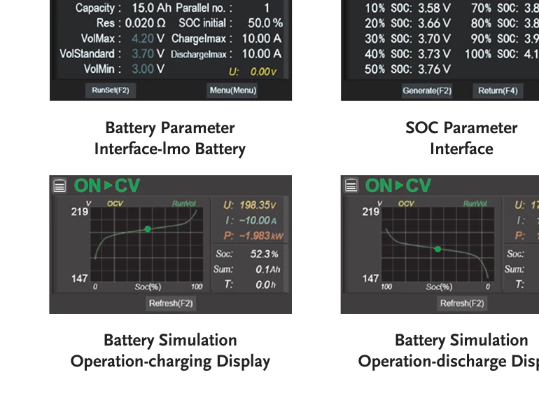
Battery simulation lets a BMS team work before the physical pack exists, and keep working when it is in somebody else’s lab: the instrument reproduces a chemistry’s voltage and current behaviour against a state-of-charge model, so the management system sees something that behaves like a battery.
Two questions decide whether it is useful to you. Is your chemistry in the list? The RBS carries eight built-in models: LMO, LCO, LFP, NCM, LTO, lead-acid, NiMH and NiCd. And is there a user-defined model? The RBS adds one custom model, which is the difference between an instrument that ages with your roadmap and one that does not. The RBS also carries a dedicated charge and discharge mode for working against a physical pack; most programmes need both halves, so confirm both are present on whatever you buy. The simulator-versus-emulator naming question, and why a plain supply fails BMS work, is covered in battery simulator vs battery emulator.
Solar Array Simulation, and Whether Your Model Has It
This is where buyers get burned. On many product families a function listed as standard is standard on some models. Solar array simulation on the RBS Series is available on models rated 500 V and above only, so a 100 V unit cannot run solar array simulation, which rules it out of PV inverter MPPT work whatever the family-level feature list implies. Never accept a feature list at family level: ask for availability against the specific model number, in writing, before the purchase order.
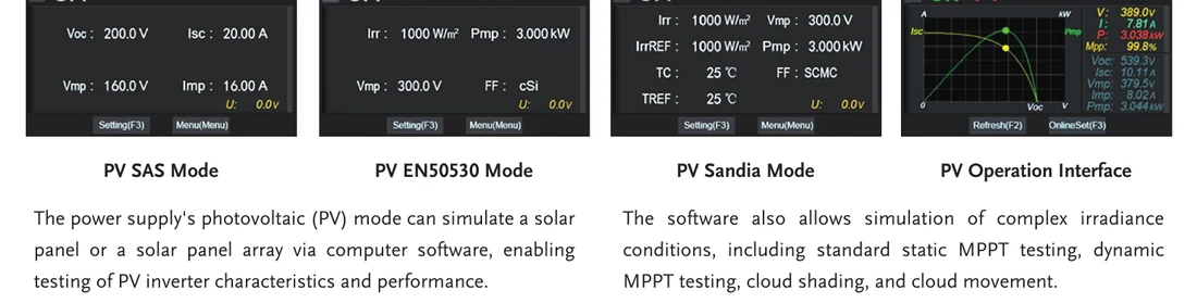
Where the function is present, look at the profiles. The RBS provides PV SAS, EN50530, Sandia, SAS2 and user-defined curves, with static and dynamic maximum power point tracking and irradiance scenarios including cloud shading and cloud movement; solar array simulation for PV inverter MPPT testing walks the workload itself. A static curve shows the algorithm can find a peak; a moving one shows whether it can follow one.
Interface Fitment Is Decided at Order Time
The RBS communication interface is one of two cards, factory-installed: the RBS-IF01 all-in-one card carrying USB, RS-232/RS-485, CAN and LAN, or the RBS-IF02 GPIB card. You choose one when you order. Not both, and not later without going back to the factory.
So know what your rack is built on before you specify. A lab standardised on GPIB with a working driver library wants the GPIB card; one automating over LAN, or needing CAN alongside the test bus, wants the all-in-one. Deciding after the crate arrives is how an instrument ends up driven from a laptop for two years.
How to Read a Transient Response Spec
A single number cannot describe a transient. The RBS specification says 2 ms, and the footnote behind it says what that means: a load step of 50% to 100% or 100% to 50%, with voltage returning to within 0.75% of rating.
That footnote is the specification. Step size, direction and settling band all move the number, and a figure quoted without them is not comparable to anything. Ask any vendor what step size, in which direction, recovering to what band. If nobody can answer, you have learned something useful about the number.
What Input Supply Does a Regenerative DC Power Supply Need?
The RBS takes a 400 V three-phase three-wire input, nominally 380 Vac to 460 Vac, accepted range 342 Vac to 510 Vac at 47 Hz to 63 Hz. An Indian facility on a standard 415 V three-phase supply sits comfortably inside that window, with room on both sides for the variation distribution here actually delivers.
Size the circuit from the power class: maximum input current at 342 Vac runs 9.2 A at 5 kW, 18.4 A at 10 kW, 27.6 A at 15 kW, 36.8 A at 20 kW and 55.2 A at 30 kW, for 5.5 kVA to 33 kVA of maximum input power at a typical power factor of 0.99. Check the room too: 0 to 40 degrees C, 20% to 90% RH, altitude to 1000 m.
Parallel Growth, So You Can Buy for Today
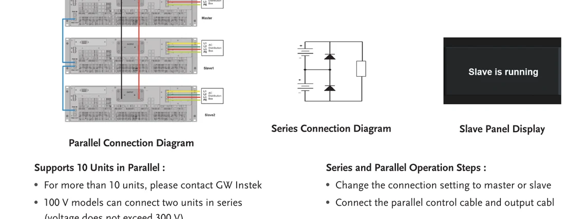
The most common budgeting mistake here is buying the power you might need in three years. All 20 RBS models support master-slave parallel operation with up to 10 identical units, and each model’s system ceiling is ten times its own rating: ten of the 30 kW models reach 300 kW, ten 5 kW units reach 50 kW. For more than 10 units, GW Instek asks you to contact them. Start with one 5 kW or 10 kW unit, prove the test method, add matched units as the programme grows. The 100 V models add a second axis: two can run in series, with GW Instek capping the combined voltage at 300 V. Get the parallel limit in writing, for the model rather than the family.
Which Protections Should You Ask For?
The obvious three are over-voltage, over-current and over-temperature. On the RBS, OVP and OCP are settable across 0 to 110% of full scale, with OTP alongside. Two more are worth naming: remote-sense reverse protection, which guards against Vsense leads connected backwards, and input over-voltage and under-voltage protection, which guards the instrument against the supply itself. Ask for the full list, not the headline three.
Questions to Ask Any Vendor
- What is the sink-mode efficiency, and where does the absorbed energy go? Confirm the figure and the direction.
- What are the voltage and current ceilings for the exact model number, in source and in sink? Including the sink-mode minimum.
- How many kilowatts per rack unit, and what does the chassis weigh?
- What is the parallel limit for this model, and does maximum system power assume identical units?
- Which battery chemistries are built in, and is there a user-defined model?
- Is solar array simulation available on this model number? Not on the family. On the model.
- Which communication interface am I getting, and can it change after delivery?
- What are the conditions behind the transient response figure? Step size, direction, settling band.
- What is the complete protection suite? Including remote-sense and input-side protection.
- Who supports and calibrates this locally, and on what turnaround? An instrument that leaves the country for calibration is out of service far longer than the paperwork suggests.
Which Voltage and Power Class Suits Your Industry
EV and Two-Wheeler Programmes
Homologation cycling under AIS 156 and AIS 038 is where bidirectional operation and energy recovery pay for themselves; our companion piece on regenerative DC testing for EV validation covers those workloads in depth. For selection: a two-wheeler or three-wheeler programme usually lands in the 100 V class, where the question is current rather than voltage; most passenger and commercial traction packs land at 500 V; and a pack marketed as an 800 V architecture needs its top-of-charge measured against the 750 V ceiling, which moves some programmes to the 1000 V class. If BMS validation is on the plan, weigh the battery-simulation chemistry list as heavily as the ratings.
Energy Storage and BESS
Grid-tied storage qualification is continuous-cycling work at rack level, and the economics drive the selection. Sourcing the DC bus at utility-typical voltages puts you in the 1000 V, 1500 V or 2250 V classes depending on the stack, and regeneration on the discharge side turns a test that would be prohibitive on a resistive load into a routine one. These programmes run for weeks, so protection coverage matters as much as ratings.
PV Inverter Validation
Solar inverter work is the clearest case of a feature deciding the model. You need solar array simulation, which puts you at 500 V or above, and the voltage class then follows the string you are reproducing, typically 1000 V or 1500 V. Look for static and dynamic MPPT and for irradiance profiles such as cloud shading and cloud movement. Validating indoors on demand also takes the weather out of your schedule.
Motor Drives
A motor-drive bench traditionally needs a DC supply for the bus, a blocking diode to stop reverse current, and a separate load to absorb what the drive regenerates under braking. A bidirectional regenerative instrument is the bus and the load at once, and returns the braking energy instead of heating the room with it: fewer instruments, less wiring, a cooling load that does not grow with test duration. Voltage class follows the drive’s DC bus.
Labs, Academia and General Power Electronics
For a shared lab supporting many projects, flexibility matters more than any single peak rating: programmable sequence depth, the range of load modes, and whether output resistance can be simulated to represent cable and internal-resistance effects. On the RBS, sequence programming holds up to 50 sequences of 20 steps, the load side offers constant current, voltage, power and resistance plus composite and automatic modes, and DC output resistance is settable from 0 Ohm to a per-class maximum.
Regeneration Economics, as a Selection Input
Whether the regenerative premium is recoverable is a utilisation question, and it belongs in the selection file before you fix the power class. The sizing arithmetic lives in regenerative electronic load vs traditional, and the facility-level case in why power labs are moving to energy recovery. The short version: continuous cycling and burn-in recover the premium, short intermittent tests do not, and GW Instek quotes recovery efficiency for the RBS as up to 93% in both directions.
How GSAS Helps You Specify the Right Unit
GSAS Micro Systems is an engineering partner, and on a purchase like this the engineering happens before the order. We work through the voltage and current envelope with your team, confirm which functions are available on the model number you are considering, get the interface decision right the first time, and check your three-phase supply against the instrument’s input window. If the honest answer is that your workload does not need regenerative hardware, we would rather say so at that stage.
For the GW Instek platform covered here, see RBS Series regenerative bidirectional DC source specifications and pricing. We arrange demos and evaluation units, and provide installation, calibration and after-sales support from offices in Bengaluru, Hyderabad, Chennai, Pune, Mumbai and Delhi NCR.
Request a quote with your device’s voltage and current envelope, and we will come back with a configuration rather than a catalogue.
Also appears in:
Interested in GW Instek tools?
Talk to our application engineers for personalized tool recommendations.
More from GW Instek
View all →
Emulating Processor Power for Thermal Testing: Why Constant Power
7 Oct · 7 min

CRPS and Rack Power Supply Testing: The Six Tests That Matter
7 Oct · 7 min

GPU Power Board Testing: DC Input Verification Before Integration
7 Oct · 6 min
Servo Motor Inrush Current Testing: Method, Limits and Bench
7 Oct · 6 min

SuperTest Van Gogh 6.0: C23, C++23 and the C++20 Modules Gap
6 Oct · 7 min

AI Inside the Engineering Process: What Is Worth Automating, and What Still Needs an Engineer
21 Sept · 11 min