
TESSY + Arm Keil MDK: Compile with AC6, Test with TESSY, Full Cortex-M Coverage
Arm Cortex-M microcontrollers dominate Indian embedded design, from automotive body controllers and ADAS sensor interfaces in Pune to industrial PLC modules in Chennai and medical device firmware in Bengaluru. The standard development environment for Cortex-M is Arm Keil MDK with Arm Compiler 6 (AC6). But compilation is only half the engineering workflow.
The other half, the part that safety standards mandate, is systematic unit testing with structural coverage measurement.
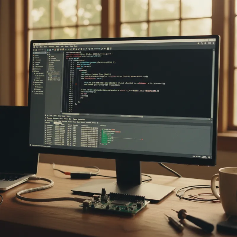
Razorcat TESSY integrates directly with Keil MDK and Arm Compiler 6, creating a workflow where engineers compile and test with the same toolchain they ship to production.
Why the Compiler Matters for Unit Testing
A common mistake in embedded unit testing is compiling test code with GCC on a Linux host while the production code compiles with AC6 for Cortex-M. The problem is that different compilers handle structure packing, bit-field ordering, integer promotion, and optimization differently. A test that passes under GCC may not reflect the actual behaviour of the code compiled under AC6.
TESSY eliminates this problem. When configured for a Keil MDK project, TESSY uses AC6 to compile the test harness, stubs, and unit under test. The compiled test code uses the same calling conventions, type sizes, alignment rules, and optimization passes as the production build. Coverage results reflect the actual production binary, not a host simulation with different compiler semantics.
Setting Up the Integration
The TESSY–Keil MDK integration requires three configuration steps:
1. Compiler configuration. In TESSY’s project settings, specify the Arm Compiler 6 executable path and the compiler flags from the Keil project. TESSY parses the project’s compile options, target CPU (Cortex-M0/M3/M4/M7/M33), optimization level, FPU settings, endianness, so the test compilation matches production exactly.
2. Include paths and defines. TESSY imports the include paths and preprocessor definitions from the Keil MDK project. CMSIS headers, device-specific startup files, and project-level defines are resolved automatically. Engineers do not need to manually replicate the Keil project’s build configuration.
3. Test execution target. Tests can run in three modes:
- Simulator: TESSY uses the Arm instruction set simulator for fast, hardware-independent execution. Suitable for logic-level unit testing where hardware peripheral access is not required.
- On-target via J-Link: Tests download to the Cortex-M device through a SEGGER J-Link debug probe and execute on real hardware. Coverage data is read back through the debug channel. This is the preferred mode for safety-critical projects where assessors require target-based evidence.
- On-target via ULINKplus: For teams using Arm’s own debug probe, TESSY supports ULINKplus for target execution and power measurement.
The Testing Workflow
Once configured, the daily engineering workflow is:
- Write or modify firmware in Keil MDK (uVision or VS Code with Keil extension)
- Open the module in TESSY: TESSY’s automatic interface analysis parses the function signatures, identifies parameters, return types, global variables, and called functions
- Design test cases using the Classification Tree Editor (equivalence classes, boundary values) or directly in the tabular test data editor
- Configure stubs for called functions, define return values and side effects per test case
- Execute tests: TESSY compiles with AC6, runs on simulator or target, and measures coverage
- Review coverage: colour-coded source view shows which statements, branches, and MC/DC conditions are covered
- Generate reports: HTML or PDF reports with coverage matrices and requirements traceability for safety case inclusion
Steps 2 through 7 happen inside TESSY. The Keil MDK project and TESSY project coexist, TESSY reads the Keil build configuration but does not modify it.
CI/CD Pipeline Integration
For teams running continuous integration (common among automotive Tier-1 suppliers in Pune and Hyderabad serving European OEMs), the workflow extends into the CI pipeline:
- Developer pushes code to GitLab/GitHub
- CI pipeline triggers a TESSY batch execution (command-line mode)
- TESSY compiles all affected modules with AC6 and runs test suites
- Coverage reports are generated and compared against thresholds (e.g., 100% MC/DC for ASIL D functions)
- Pipeline passes or fails based on coverage gates
- Reports are archived as build artifacts for audit trail
This automation ensures that no code change reaches the integration branch without passing the coverage requirements defined by the safety plan.
Coverage Metrics for Cortex-M Code
TESSY measures MC/DC coverage on the instrumented AC6-compiled code. For Cortex-M4 and M7 firmware using hardware FPU instructions, conditional branches related to floating-point comparisons are instrumented and covered. For Cortex-M33 with TrustZone, TESSY handles secure/non-secure function calls through its stub mechanism.
The coverage report maps directly to the AC6-compiled source, so engineers and assessors see coverage results that correspond to the code the compiler actually generates, not a host-compiled approximation.
Why Buy from GSAS
GSAS Micro Systems is the authorized partner for both Razorcat (TESSY) and Arm (Keil MDK). This means a single local partner for the complete compile-and-test workflow, with INR invoicing, joint onboarding training, and integrated technical support. Our engineers in Bengaluru, Hyderabad, Chennai, Pune, Mumbai, and Delhi NCR configure the TESSY–Keil MDK integration on your project, train your team on the Classification Tree Method, and help set up CI/CD quality gates for MC/DC coverage.
Also appears in:
Interested in Razorcat tools?
Talk to our application engineers for personalized tool recommendations.
More from Razorcat
View all →
Test Case Design with the Classification Tree Method: Deriving Unit Tests You Can Defend in an Audit
1 Aug · 10 min
Fault Injection and Robustness Testing for Embedded Software: What ISO 26262, IEC 61508 and DO-178C Actually Ask For
1 Aug · 11 min
How to Evaluate a Unit Testing Tool for Embedded Software: A Buyer's Framework for Indian Teams
1 Aug · 10 min
Is 100% Code Coverage Enough? Statement, Branch, MC/DC and MCC, and What Each One Proves
1 Aug · 9 min

Emulating Processor Power for Thermal Testing: Why Constant Power
7 Oct · 7 min

CRPS and Rack Power Supply Testing: The Six Tests That Matter
7 Oct · 7 min


