
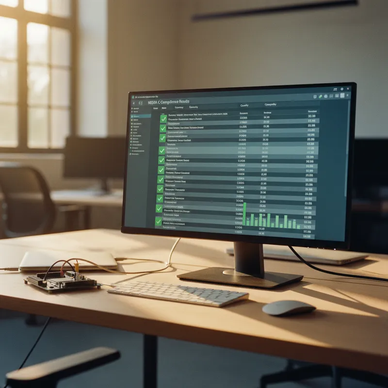
TESSY on Infineon AURIX TC3xx: Unit Testing Safety-Critical Motor Control Firmware
The Infineon AURIX TC3xx is the safety microcontroller of choice for automotive powertrain, chassis, and ADAS applications. Its TriCore architecture delivers the real-time performance, hardware safety mechanisms (lockstep cores, ECC memory, safety management unit), and ASIL D certification support that safety-critical ECU designs require.
Indian automotive Tier-1 suppliers in Pune, Bengaluru, and Chennai use AURIX TC3xx extensively, for engine management units, inverter controllers, electric power steering, and battery management systems. These teams need unit testing tools that understand the TriCore architecture, compile with the project’s cross-compiler, and deliver MC/DC coverage evidence suitable for ISO 26262 ASIL D certification.
Razorcat TESSY provides exactly this capability.
Why AURIX Testing Is Different
Unit testing code for an AURIX TC3xx device is not the same as testing code for a Cortex-M. The TriCore architecture has specific characteristics that affect the testing workflow:
Multi-core architecture. TC3xx devices have up to six TriCore cores (TC1.6P performance cores + TC1.6E efficiency cores). Safety-critical functions may be allocated to specific cores, with lockstep execution on safety cores. The unit testing tool must compile for the correct core type.
Compiler-specific behaviour. AURIX projects use either the TASKING VX-toolset or the HighTec GCC-based compiler. Both compilers have TriCore-specific optimizations, intrinsic functions, and memory qualifiers (near/far addressing, core-local vs shared memory) that affect code generation. The testing tool must use the same compiler to produce meaningful coverage data.
Safety mechanisms. AURIX TC3xx includes hardware safety mechanisms, memory protection units, trap vectors, safety endbits, that interact with the software. While unit tests typically stub out hardware interactions, some safety-relevant functions (fault reaction, safety monitor tasks) need to be tested in a way that accounts for these mechanisms.
AUTOSAR integration. Most Indian AURIX projects use an AUTOSAR Classic stack, typically Elektrobit tresos or Vector DaVinci for BSW configuration. The application software is structured as AUTOSAR Software Components (SWCs) communicating through the Runtime Environment (RTE). Unit testing must isolate SWC logic from the RTE and BSW dependencies.
TESSY’s AURIX Support
TESSY handles AURIX-specific requirements through its compiler integration and target execution framework:
TriCore Compilation
TESSY configures the TASKING VX-toolset or HighTec compiler as its build environment. The test harness, stubs, and unit under test compile with the same compiler options, optimization levels, and TriCore-specific settings as the production build. Memory qualifiers, intrinsic functions, and compiler-specific extensions are handled correctly because TESSY uses the actual project compiler, it does not translate or rewrite the source code.
For teams in Pune using TASKING for AURIX TC3xx powertrain ECUs, TESSY imports the TASKING project configuration so that test compilation exactly matches the production build.
On-Target Execution via J-Link
TESSY downloads test binaries to the AURIX device through a SEGGER J-Link debug probe. J-Link supports the AURIX Debug Access Port (DAP) for both TriCore and GTM coprocessor access. Tests execute on the target, and coverage data is read back through the debug channel.
On-target execution matters for AURIX because:
- TriCore’s instruction set and register architecture differ from x86, host-based simulation cannot replicate the exact behaviour
- TASKING’s optimization passes (especially at -O2 and -O3) restructure the code significantly, coverage measured on the host does not represent the optimized target code
- Safety assessors reviewing ASIL D projects expect target-based coverage evidence
AUTOSAR SWC Isolation
TESSY generates stubs for AUTOSAR RTE interfaces automatically. When testing an SWC’s runnable entities, TESSY stubs Rte_Read, Rte_Write, Rte_Call, and other RTE API functions so that the SWC logic is tested in isolation from the BSW stack.
This approach is AUTOSAR stack-agnostic. Whether the project uses Elektrobit tresos, ETAS ISOLAR, or Vector DaVinci for AUTOSAR configuration, TESSY tests the SWC at the C source level without depending on the configuration tool.
Typical AURIX Testing Workflow
For a powertrain ECU project on TC3xx:
- Import the TASKING/HighTec project configuration into TESSY, compiler paths, include directories, preprocessor defines, target device
- Select modules to test: motor control algorithms, torque calculation, fault detection, diagnostic handlers
- Automatic interface analysis: TESSY parses each function to identify parameters, return types, global variables, and called functions
- Design test cases: use the Classification Tree Editor for systematic boundary value and equivalence class testing (highly recommended for ASIL D)
- Configure stubs: define return values for MCAL functions, RTE interfaces, and utility library calls
- Execute on target: TESSY compiles with TASKING, downloads via J-Link, executes on AURIX, collects MC/DC coverage
- Generate reports: HTML/PDF reports with coverage matrices, test case results, and requirements traceability (ReqIF)
Coverage Targets for ASIL D
ISO 26262 Part 6 gives MC/DC its strongest recommendation at ASIL D unit testing. For AURIX powertrain functions with complex conditional logic (torque limit calculations, fault escalation state machines, diagnostic trouble code logic), achieving 100% MC/DC requires careful test case design.
TESSY’s Classification Tree Editor makes this manageable by decomposing complex input spaces into equivalence classes and generating test vectors that exercise each atomic condition independently. The colour-coded coverage display highlights uncovered MC/DC conditions, directing engineers to the specific test cases needed to close coverage gaps.
Why Buy from GSAS
GSAS Micro Systems is the authorized Razorcat partner, providing TESSY licensing for AURIX TC3xx projects with INR invoicing, TASKING/HighTec compiler integration support, and ISO 26262 tool qualification consulting. Our engineers in Bengaluru, Hyderabad, Chennai, Pune, Mumbai, and Delhi NCR have direct experience configuring TESSY for AURIX-based powertrain and chassis ECU projects. We also supply SEGGER J-Link probes for on-target test execution, giving your team a complete compile-test-debug workflow from a single Indian partner.
Also appears in:
Interested in Razorcat tools?
Talk to our application engineers for personalized tool recommendations.
More from Razorcat
View all →
Test Case Design with the Classification Tree Method: Deriving Unit Tests You Can Defend in an Audit
1 Aug · 10 min
Fault Injection and Robustness Testing for Embedded Software: What ISO 26262, IEC 61508 and DO-178C Actually Ask For
1 Aug · 11 min
How to Evaluate a Unit Testing Tool for Embedded Software: A Buyer's Framework for Indian Teams
1 Aug · 10 min
Is 100% Code Coverage Enough? Statement, Branch, MC/DC and MCC, and What Each One Proves
1 Aug · 9 min

Emulating Processor Power for Thermal Testing: Why Constant Power
7 Oct · 7 min

CRPS and Rack Power Supply Testing: The Six Tests That Matter
7 Oct · 7 min


