
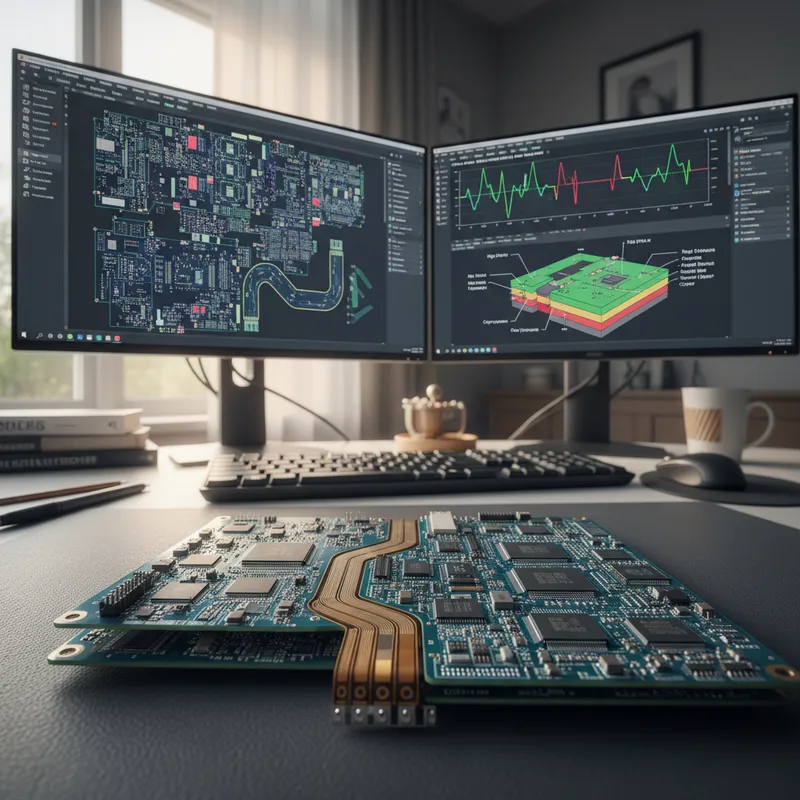
RIGID-FLEX DESIGN IN ALTIUM DESIGNER
Rigid-flex PCB technology offers a tremendous amount of benefits, including reduced weight, space, increased durability, and reliability. Today’s small, lightweight mil-aero, medical, and consumer electronics products are best implemented with rigid-flex technology. However, not every PCB design tool offers the capabilities necessary for achieving successful rigid-flex PCB designs on time.
Timing:
Thursday, 03rd December 2020 | 02:30 PM to 03:30 PM
Here are just some key points you can expect to walk away with:
- Why Rigid-Flex
- Flex Materials
- Routing Tips
- Polygons Placement
Recorded Live-webinar
What rigid-flex really demands from a PCB tool
Rigid-flex isn’t just about drawing flexible sections in the layer stack. The tool needs to model bend regions, stagger transitions through coverlays correctly, route across the rigid-to-flex boundary without DRC false-positives, handle variable layer counts in different zones of the board, and produce manufacturing data that the fabricator can build from without back-and-forth queries. Indian medical-wearable, defence, and aerospace teams adopting rigid-flex hit each of these stress points within the first few projects.
How Siemens Xpedition handles rigid-flex
GSAS Micro Systems is an authorized engineering partner in India. Xpedition Enterprise treats rigid-flex as a first-class design intent rather than a layered drawing exercise, bend regions, coverlay transitions, and per-zone stack-up changes are modelled in the design database, propagated through routing rules, validated against fabricator capabilities through Valor NPI sign-off, and rendered correctly in the 3D view that ECAD/MCAD co-design relies on. Xpedition Standard offers rigid-flex via its token-based add-on for individual engineers and small teams.
The choice for an Indian rigid-flex team usually comes down to project scale: Xpedition Standard with the rigid-flex token covers the typical 4-6 layer rigid section + 1-2 layer flex section that most consumer-electronics and IoT wearables ship. Xpedition Enterprise becomes the right answer when a programme has multiple boards interconnected through rigid-flex (military electronics, advanced medical instruments, satellite payloads), multiple geographically distributed designers on one design, or HyperLynx SI sign-off requirements on the routed product.
For a deeper head-to-head, see our Altium Designer vs Siemens Xpedition Standard for Indian PCB teams comparison.
Also appears in:
Need embedded development tools?
Talk to our application engineers for personalized tool recommendations.





