
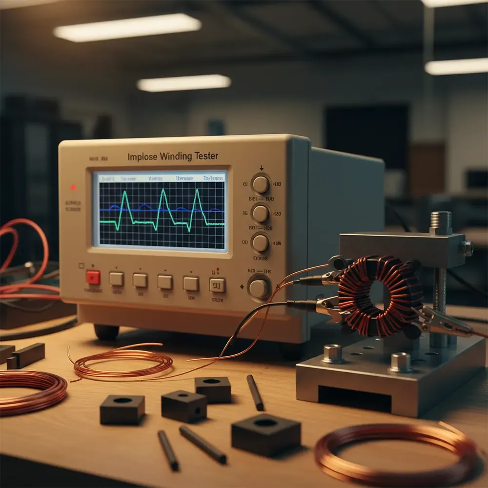
Transformers and inductors are the magnetic heart of every power converter. Whether it is a 5 W USB charger, a 50 kW EV on-board charger, or a 500 kVA industrial UPS, the magnetic components define the converter’s efficiency, thermal behavior, and reliability. A defective transformer does not just fail, it can cause cascading damage to semiconductors, capacitors, and downstream circuits, turning a single winding defect into a costly field failure.
Testing these components requires two fundamentally different approaches: parametric measurement (turns ratio, inductance, DCR, leakage) verifies that the transformer meets its electrical design specifications, while impulse winding analysis detects physical defects, shorted turns, layer shorts, and insulation weakness, that parametric methods cannot see. Understanding both approaches, and why production lines need both, is essential for anyone manufacturing or inspecting magnetic components.
The Transformer Equivalent Circuit
Every transformer can be modeled as an equivalent circuit of ideal and parasitic elements. Understanding these parameters is the foundation for both transformer design and test specification.
Turns ratio is the ratio of primary to secondary winding turns, which determines the voltage transformation ratio. In an ideal transformer, the voltage ratio equals the turns ratio exactly. In a real transformer, winding resistance and leakage inductance cause the actual voltage ratio to deviate from the ideal under load. Turns ratio is measured by applying a known AC voltage to one winding and measuring the induced voltage on the other. Magnetizing inductance is the inductance seen looking into the primary winding with the secondary open-circuited. It determines how much magnetizing current flows to establish the core flux, a key parameter for converter control loop design and efficiency at light loads. Leakage inductance represents the magnetic flux that links one winding but not the other. It appears as a series inductance in the equivalent circuit and stores energy that must be dissipated or recovered during switching transitions. In flyback converters, leakage inductance causes voltage spikes on the primary switch; in forward converters, it limits the maximum duty cycle. Leakage inductance is measured by shorting the secondary and measuring the inductance from the primary, the remaining inductance is almost entirely leakage. DC resistance (DCR) is the copper resistance of each winding, measured with a DC signal to exclude inductive effects. DCR determines copper loss (I-squared-R heating) and directly affects transformer temperature rise and converter efficiency. For multi-winding transformers, each winding has its own DCR specification. Interwinding capacitance is the parasitic capacitance between primary and secondary windings, determined by the winding geometry, insulation thickness, and dielectric constant. This capacitance provides a coupling path for common-mode noise and affects EMI performance.
The Microtest Transformer Test System (5260 series) measures all of these parameters in automated sequences: turns ratio, inductance, DCR, leakage inductance, interwinding capacitance, polarity, phase, hipot withstand, and insulation resistance. A complete parametric profile takes seconds, with pass/fail limits on every parameter and SPC logging for trend analysis.
Why Parametric Tests Are Not Enough
Here is the critical insight that separates adequate quality control from excellent quality control: a transformer can pass every parametric measurement and still have a defect that will cause field failure.
Consider a single shorted turn in a 100-turn winding. The short reduces the effective turns count by one, a 1% change in turns ratio that may fall within the turns ratio tolerance. The short reduces the winding DCR by the resistance of one turn, perhaps 0.5% of the total, well within the DCR specification. The short slightly reduces magnetizing inductance and slightly increases leakage inductance, but these changes may also fall within tolerance.
Yet that single shorted turn creates a closed loop of copper around the core. Every time the core flux changes, it induces a large circulating current in that shorted turn. This circulating current generates localized heating that progressively degrades the winding insulation, eventually causing the transformer to fail in the field, weeks, months, or years after it passed every parametric test on the production line.
This is where impulse winding analysis becomes essential.
Impulse Winding Test Theory
The impulse winding test detects shorted turns and insulation defects by exploiting a physical principle that parametric measurements cannot access: the resonant behavior of the winding structure.
The test applies a fast voltage impulse, a controlled pulse with a defined rise time and amplitude, to the winding under test. This impulse excites the distributed inductance and capacitance of the winding structure, producing a damped oscillation (ringing waveform) whose frequency, amplitude, and decay rate are determined by the winding’s physical geometry, the core material properties, and the insulation integrity.
A shorted turn changes the winding’s distributed parameters, altering the resonant frequency and damping characteristics of the impulse response. Even a single shorted turn that is invisible to DCR and inductance measurements produces a clear, measurable shift in the impulse waveform, because the circulating current in the shorted turn loads the winding differently than an intact turn.
The test procedure works as follows:
1. Reference waveform capture: A known-good transformer (golden sample) is impulse-tested, and its waveform is stored as the reference.
2. DUT impulse test: The production transformer receives the same impulse, and its response waveform is captured.
3. Waveform comparison: The tester compares the DUT waveform against the reference using multiple analysis algorithms.
4. Pass/fail decision: If the waveform deviation exceeds the programmed threshold, the unit fails.
Comparison Methods: Area, Differential, and Flutter
The Microtest Impulse Winding Tester uses three complementary comparison algorithms to maximize defect detection while minimizing false rejects.
Area comparison calculates the total area enclosed between the DUT waveform and the reference waveform. Shorted turns reduce the oscillation amplitude and shift the frequency, increasing the area difference. Area comparison is the most commonly used method and catches the majority of winding defects. Differential analysis examines the point-by-point difference between the DUT and reference waveforms, highlighting localized deviations that might be diluted in the area calculation. This method is particularly sensitive to partial shorts and layer-to-layer insulation weakness. Flutter analysis detects intermittent defects, marginal contacts, loose turns, and insulation that breaks down only momentarily under the impulse voltage stress. The tester applies multiple consecutive impulses and analyzes the variation between successive DUT waveforms. A stable winding produces identical waveforms on every pulse; an intermittent defect causes pulse-to-pulse variation (flutter).
Progressive Voltage Stress Testing
Beyond detecting existing defects, the impulse test can reveal insulation weakness by progressively increasing the impulse voltage. The tester applies impulses at increasing voltage levels, for example, starting at 500 V and stepping up in 100 V increments. At each voltage level, the waveform is compared against the reference captured at the same voltage.
If the insulation between turns or layers is marginal, it will break down at some voltage below the rated impulse withstand level, producing a sudden waveform change. This progressive stress test catches insulation defects that would not manifest at the normal operating voltage but would fail under transient overvoltage conditions in the field, such as lightning surges, load dump events, or switching transients.
Production Integration: Catching Defects Early
The economic argument for impulse winding testing is strongest when the test is performed during the winding process rather than after final assembly. A shorted turn detected while the bobbin is still on the winding machine costs the manufacturer one bobbin and a few minutes of rewinding. The same defect detected after the transformer has been potted, encapsulated, and assembled into a finished product costs an entire product assembly plus the cost of disassembly, rework, and retest.
The Microtest Impulse Winding Tester is designed for in-process deployment on the winding floor. The operator tests each winding immediately after the winding operation, before the transformer proceeds to assembly, potting, or encapsulation. Defective windings are caught and rejected at the point of lowest scrap cost.
For complete production coverage, the impulse winding tester works in tandem with the Microtest Transformer Test System. The impulse test catches physical defects (shorted turns, insulation weakness) during winding, while the parametric test system verifies electrical specifications (turns ratio, inductance, DCR, leakage, hipot) on the finished transformer. Together, they provide end-to-end quality coverage from raw winding through finished product.
India Context: Power Electronics and EV Manufacturing
India’s power electronics manufacturing sector is expanding rapidly, driven by EV adoption, renewable energy inverter production, telecom infrastructure, and industrial automation. Every one of these sectors relies on custom-wound transformers and inductors: EV on-board chargers, DC-DC converters, solar inverters, telecom rectifiers, and industrial UPS systems all contain magnetic components that must be manufactured and tested at volume.
Indian transformer and inductor manufacturers serving these markets face the dual challenge of scaling production volume while maintaining the quality levels that OEM customers demand. Impulse winding testing provides the defect detection capability that parametric tests alone cannot deliver, and it does so at the point in the production process where catching defects has the lowest cost impact.
Get Transformer Testing Support from GSAS India
GSAS Micro Systems is an authorized Microtest partner in India, providing transformer test systems and impulse winding testers to magnetic component manufacturers across the country. Our applications engineering team supports the complete deployment workflow: reference waveform setup, impulse voltage selection, comparison threshold optimization, test sequence programming, fixture design, and handler interface configuration for automated production lines. Contact us from Bengaluru, Chennai, Hyderabad, Delhi NCR, Mumbai, or Pune for a production-line assessment, instrument demonstration, and INR pricing on Microtest transformer testing solutions.
Also appears in:
Interested in Microtest tools?
Talk to our application engineers for personalized tool recommendations.
More from Microtest
View all →
Power Measurement for Server PSUs: Microtest 7140 Power Analyzer
7 Apr · 5 min

Wireless Charger QC Testing with the Microtest 9901
7 Apr · 5 min

Motor Stator Testing in EV Manufacturing: Microtest MT-6910 Series
7 Apr · 5 min

PCB Incoming Inspection with Multichannel LCR Testing
6 Apr · 5 min

Emulating Processor Power for Thermal Testing: Why Constant Power
7 Oct · 7 min

CRPS and Rack Power Supply Testing: The Six Tests That Matter
7 Oct · 7 min


