Computer Aided Reliability Engineering - CARE

Computer Aided Reliability Engineering - CARE

GSAS Engineering · · 1 min read

Computer Aided Reliability Engineering (CARE)

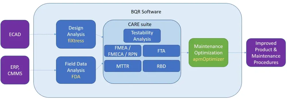
BQR’s CARE software suite is an integrated one-stop shop for all RAMS analyses, integrated with CAD tools. CARE provides a complete solution to the needs of reliability engineers, mostly used during product design or operation to improve robustness and reliability.

The complexity of critical systems is on the rise, and so is the workload of reliability engineers. BQR’s CARE suite gives reliability engineers the tools to organize technical and reliability data, conduct RAMS analyses (Reliability, Availability, Maintainability and Safety) in an integrated form concurrently and to easily produce reports.

CARE together with the fiXtress include Plug-In modules to popular CAD tools to automatically retrieve all design data applicable to RAMS analysis.

Benefits

  • Save time and effort to reliability engineers
  • Comply with international standards
  • Simple yet powerful user interface
  • Accurate and fast calculations
  • Quick and intuitive
  • Gain insight into product RAMS for improved design
  • Faster and better organized than simple Excel sheets or manual procedures
Also appears in:

Interested in BQR tools?

Talk to our application engineers for personalized tool recommendations.

Stay in the Loop

Get monthly compliance updates, product insights, and engineering best practices delivered to your inbox.

Related Articles

Embedded development bench, illustrating the hardware debug loop an AI agent can now drive, supported in India by GSAS
J-Link SEGGER

An AI Agent That Drives the Debugger: SEGGER and Embedder Connect J-Link to the Loop

SEGGER has given an AI coding agent direct control of J-Link and J-Trace: flash, breakpoints, memory inspection and live RTT on real silicon. The loop only works if the probe can read target RAM while the core runs, and GSAS field engineers know exactly where that breaks first.

13 Sept 2026 · 6 min read
The bench to harness adapter path drawn left to right: the ECU connector, a test lead, a media converter or pluggable T1 module, RJ45, and the host, showing where each connector family sits between the device under test and the laptop, from GSAS Micro Systems India
Automotive Ethernet Automotive & Mobility

Automotive Ethernet Connectors: H-MTD, MATEnet, MQS

An ECU arrives on the bench with a connector nobody has a mate for, and the day is gone. Search the family names and you get connector product pages that describe their own part and stop there. This article puts the families side by side in one table using only what their public pages state, then makes the point those pages leave out: the IEEE link segment definition, not the connector, is what sets reach and loss limits, and shielding is a channel decision rather than a preference. Written by the GSAS Micro Systems engineering team in India.

29 Aug 2026 · 12 min read
Ladder chart of the T1 single-pair Ethernet family by data rate: 10BASE-T1S (802.3cg), 100BASE-T1 (802.3bw), 1000BASE-T1 (802.3bp), 2.5/5/10GBASE-T1 (802.3ch) and 25GBASE-T1 (802.3cy), one balanced pair across five IEEE standards, from GSAS Micro Systems India
Automotive Ethernet Automotive & Mobility

The T1 Family Explained: 10BASE-T1S to Multi-Gig 802.3ch

The T1 family is the set of single-pair Ethernet physical layers used in vehicles, and every member is documented separately inside a different datasheet. This guide puts all of them in one table with rate, symbol rate, line code, specified reach and cabling traced to public IEEE task force documents, then answers the two questions that keep coming back: why 100BASE-T1 has no auto-negotiation, and why one end has to be master. Written by the GSAS Micro Systems engineering team in India.

29 Aug 2026 · 13 min read