
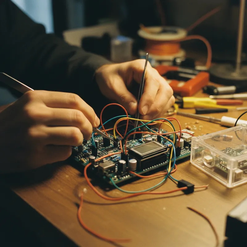
Starting FPGA development is harder than it should be. The tools are powerful but complex, the documentation assumes prior knowledge, and the gap between “I have a board” and “I have a working design running on it” is wider than most engineers expect coming from a microcontroller background. This guide bridges that gap for Indian engineers using Digilent boards (Arty A7, Basys 3, or any Xilinx-based Digilent board) with AMD/Xilinx Vivado Design Suite.
Step 1: Install Vivado
Download Vivado Design Suite from the AMD/Xilinx website. The free “Vivado ML Standard” edition supports all Artix-7, Spartan-7, and Zynq-7000 devices, covering the Arty A7, Basys 3, Arty S7, Cmod A7, and Zynq-based Digilent boards. No license purchase is needed for these device families.
Installation considerations for Indian teams:
- Disk space. Vivado requires 30-50 GB depending on the installation options. Select only the device families you need (Artix-7 for Arty/Basys, add Zynq if using Eclypse Z7 or Arty Z7) to minimise the install size.
- Download time. The installer is large (10+ GB). On typical Indian broadband connections, plan for a substantial download window or use the web installer that downloads components incrementally.
- Operating system. Vivado runs on Windows 10/11 and Linux (Ubuntu, CentOS/RHEL). macOS is not natively supported, Mac users need a Linux virtual machine or dual-boot setup.
Step 2: Install Digilent Board Files
Vivado does not include Digilent board definitions by default. The board files tell Vivado about the physical I/O connections on your specific board, which FPGA pins connect to LEDs, switches, buttons, Ethernet, DDR memory, and Pmod connectors.
Download the board files from Digilent’s GitHub repository and copy them to the Vivado board_files directory. This step is small but critical, without board files, you must manually specify every I/O constraint.
Step 3: Create a New Project
In Vivado, create a new RTL project. When prompted for the target board, select your Digilent board (e.g., “Arty A7-35T” or “Basys 3”) from the board list. This automatically configures the project for the correct FPGA device and imports the board I/O constraints.
Select your HDL language: VHDL or Verilog. Both are fully supported. In Indian universities, VHDL is slightly more common in undergraduate courses, while Verilog is more common in industry and graduate-level work. The choice does not affect the hardware capability.
Step 4: Write Your First Design
Start with the simplest possible design, one that confirms the toolchain works end-to-end:
A design that connects switches to LEDs. On the Basys 3, connect switches[15:0] to LEDs[15:0]. Each switch controls its corresponding LED. This is one line of VHDL or Verilog (a simple assignment), but it exercises the complete FPGA workflow: source entry, synthesis, implementation, bitstream generation, and hardware programming.
In Verilog:
module top(
    input  [15:0] sw,
    output [15:0] led
);
    assign led = sw;
endmodule
In VHDL:
library IEEE;
use IEEE.STD_LOGIC_1164.ALL;

entity top is
    Port ( sw  : in  STD_LOGIC_VECTOR(15 downto 0);
           led : out STD_LOGIC_VECTOR(15 downto 0));
end top;

architecture Behavioral of top is
begin
    led <= sw;
end Behavioral;
Step 5: Add Constraints
If you selected the Digilent board during project creation, the board’s master constraint file is available. Add it to your project and uncomment the lines for the I/O ports you are using (switches and LEDs in this case). The constraint file maps signal names in your HDL to physical FPGA pins.
Step 6: Synthesise, Implement, Generate Bitstream
Click “Generate Bitstream” in Vivado. This runs the complete flow:
- Synthesis: translates your HDL into a gate-level netlist
- Implementation: maps the netlist onto the FPGA’s physical resources (LUTs, flip-flops, routing)
- Bitstream generation: creates the configuration file that programmes the FPGA
For a simple design, this takes 1-3 minutes. Complex designs on larger FPGAs can take 30-60 minutes.
Step 7: Programme the FPGA
Connect your Digilent board via USB. Vivado’s Hardware Manager detects the board’s built-in JTAG programmer. Open the hardware target, select your device, and programme the bitstream.
Within seconds, the FPGA is configured. Toggle the switches, the LEDs follow. Your first FPGA design is running on real hardware.
What Comes Next
With the toolchain working, the natural progression:
- Combinational logic: adders, multiplexers, decoders, ALU
- Sequential logic: counters, shift registers, state machines (using the 100 MHz on-board clock)
- Seven-segment display: multiplexed display driving (Basys 3) or LED PWM control (Arty A7)
- UART communication: serial interface to PC via USB-UART
- Memory interfaces: block RAM usage, and DDR3L on the Arty A7
- Soft processor: MicroBlaze or RISC-V implementation
- Pmod peripherals: ADC, DAC, sensors, displays
Each step builds on the previous, and the Digilent board ecosystem (Pmod modules, reference designs, tutorial documentation) supports the learning path.
Why Buy from GSAS
GSAS is an authorized partner in India, providing Arty A7, Basys 3, and the full Digilent board and Pmod portfolio with INR invoicing, local stock, and technical support. We serve engineers and institutions across Bengaluru, Hyderabad, Chennai, Pune, Mumbai, Delhi NCR, and Visakhapatnam.
Also appears in:
Interested in Digilent tools?
Talk to our application engineers for personalized tool recommendations.
More from Digilent
View all →
Real-World SDR Applications: 5G Research, Satellites, IoT and ADS-B
28 Aug · 6 min
What Is Software Defined Radio (SDR)? A Practical Explainer for Indian Engineering Teams
19 Aug · 9 min

ZedBoard FPGA-in-the-Loop: HDL Verifier vs HDL Coder
5 Aug · 9 min

AI Data Centers in India: Test, Measurement & Memory Boom
4 Jun · 14 min

Emulating Processor Power for Thermal Testing: Why Constant Power
7 Oct · 7 min

CRPS and Rack Power Supply Testing: The Six Tests That Matter
7 Oct · 7 min


