
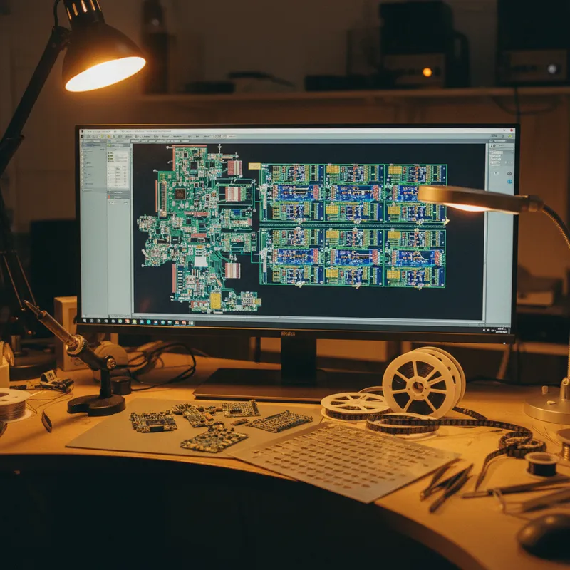
High-density interconnect (HDI) PCB technology is driven by miniaturisation: finer traces, smaller vias, thinner dielectrics, and more layers in less thickness. Smartphones, wearables, medical implants, and compact industrial controllers all demand HDI designs with features that push electroplating beyond the comfort zone of conventional process control.
The plating challenges in HDI are qualitatively different from standard PCB fabrication. Where a conventional 8-layer board might have 150-micrometre traces and 300-micrometre drilled vias, an HDI design may have 75-micrometre traces, 100-micrometre laser-drilled microvias, and stacked via structures that must be copper-filled rather than simply plated. At these dimensions, the plating uniformity that was acceptable on conventional boards becomes a yield limiter on HDI.
Fine Trace Plating
As traces narrow from 150 micrometres to 75 micrometres and below, two plating effects become dominant:
Trace mushrooming. During pattern plating, copper deposits not only on the trace surface but also grows laterally over the resist edges. On wide traces, this lateral growth is a minor fraction of the total width. On fine traces, the mushrooming can represent 20-30% of the trace width, creating a trapezoidal cross-section that differs from the rectangular cross-section assumed in impedance calculations.
Current crowding at trace edges. The sharp edges of the resist pattern concentrate current, causing the trace edges to plate thicker than the centre. On fine traces, the edge-to-centre thickness variation represents a larger fraction of the total thickness, creating a non-uniform cross-section.
Both effects are electrochemical phenomena that Elsyca PCBPlate models from first principles, predicting the actual trace cross-section geometry after plating, including mushrooming and edge effects.
Microvia Filling
HDI designs use laser-drilled microvias (typically 75-150 micrometre diameter) rather than mechanically drilled through-holes. For stacked via structures, where microvias on successive layers are stacked directly on top of each other, the microvias must be copper-filled (completely filled with copper) rather than conformally plated (a thin copper lining on the barrel wall).
Copper filling requires specialised plating chemistry with bottom-up fill additives that promote deposition at the via bottom while suppressing deposition at the via mouth. The additive system must be precisely balanced, too little accelerator and the via does not fill; too much and the fill grows mushroom-shaped, creating a surface bump that prevents reliable stacking.
PCBPlate simulates the via filling process, predicting:
- Fill completeness: whether the via fills fully or leaves a void
- Surface dimple/protrusion: the flatness of the filled via surface after plating
- Fill time: how long the filling process takes for a given chemistry and current profile
For Indian fabricators building HDI capability, PCBPlate provides the process development guidance that physical trial-and-error would require dozens of experiments to establish.
Panel-Level Uniformity at HDI Tolerances
The panel-level plating variation that is tolerable on conventional boards, 5-10 micrometres of thickness variation across the panel, consumes the entire tolerance budget on HDI designs. When the nominal copper thickness is 20 micrometres and the impedance tolerance demands +/- 3 micrometres, there is no room for the 30-50% edge-to-centre variation that conventional plating cells produce.
PCBBalance addresses this by optimising the copper pattern for uniform current distribution. At HDI dimensions, the copper balance is more critical and more difficult, the fine features create sharp local gradients in copper density that coarse thieving patterns cannot compensate. PCBBalance v2.1 handles HDI layer stacks, computing the optimal copper balance for each layer including the effects of buried and blind via structures.
The Indian HDI Manufacturing Opportunity
India’s PCB manufacturing sector is at an inflection point. Government incentives and domestic demand are driving investment in HDI fabrication capacity. Facilities in Bengaluru, Pune, Chennai, and Delhi NCR are adding sequential lamination, laser drilling, and copper filling capability.
For these facilities, plating simulation is not an optional sophistication, it is a yield enabler. The cost of physical process development for HDI is high (expensive materials, long cycle times, destructive cross-section testing), and the parameter space is large (chemistry, current profile, pulse waveform, temperature, agitation). Simulation compresses the development cycle by identifying the process window virtually before committing to physical trials.
For Indian design houses creating HDI designs for domestic fabrication, Elsyca simulation verifies that the design is manufacturable on the target fabricator’s line, reducing the risk of yield problems that emerge only after fabrication.
Why Buy from GSAS
GSAS provides the Elsyca PCB simulation tools in India, PCBPlate and PCBBalance with HDI capability, alongside our Siemens EDA design tools. We support PCB fabricators and design teams in Bengaluru, Hyderabad, Chennai, Pune, Mumbai, Delhi NCR, and Visakhapatnam with licensing, training, and process simulation consulting.
Also appears in:
Interested in Elsyca tools?
Talk to our application engineers for personalized tool recommendations.
More from Elsyca
View all →
Elsyca PCBPlate: How Panel Plating Simulation Predicts Copper Thickness Before Fabrication
5 Apr · 6 min

Elsyca PlatingManager: Digital Twin Simulation for Industrial Electroplating Lines
4 Apr · 5 min

Copper Thieving for PCBs: Why Manual Methods Fail and How Simulation Fixes It
3 Apr · 5 min
Via Plating Reliability: Why Thin Barrels Fail and How Simulation Prevents It
2 Apr · 5 min

Emulating Processor Power for Thermal Testing: Why Constant Power
7 Oct · 7 min

CRPS and Rack Power Supply Testing: The Six Tests That Matter
7 Oct · 7 min


